(a) Using Network RTK to Self-Position
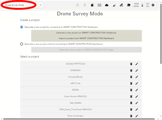
Set Edge to Drone Survey Mode
Before setting the EdgeBox location using Network RTK, you must configure APN settings and Network RTK account settings.
For details, please refer below.
To use Network RTK, an LTE service and a NTRIP Service are required.
-
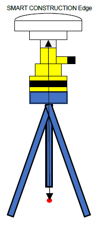
Place EdgeBox on site on a tripod or 5/8 thread bolt with a clear view of the sky.
The main unit should be fixed securely.
Unsecure installation may incur data inaccuracy, error or failure and damage to the Edge.
-
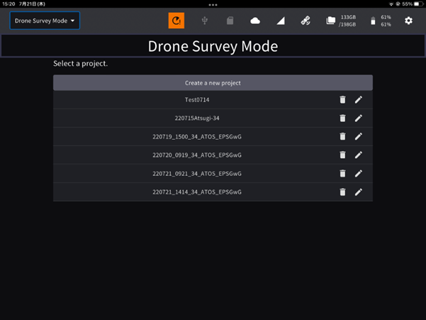
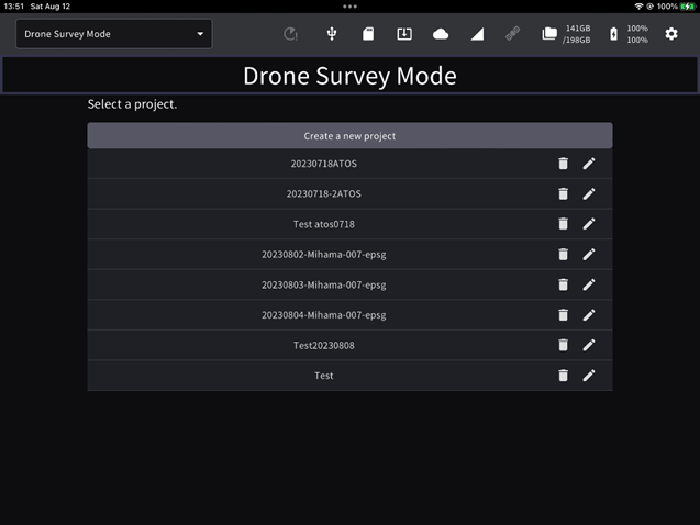
Launch the tablet app and select a project of the work site to survey.
If the project is not listed, create a new project..
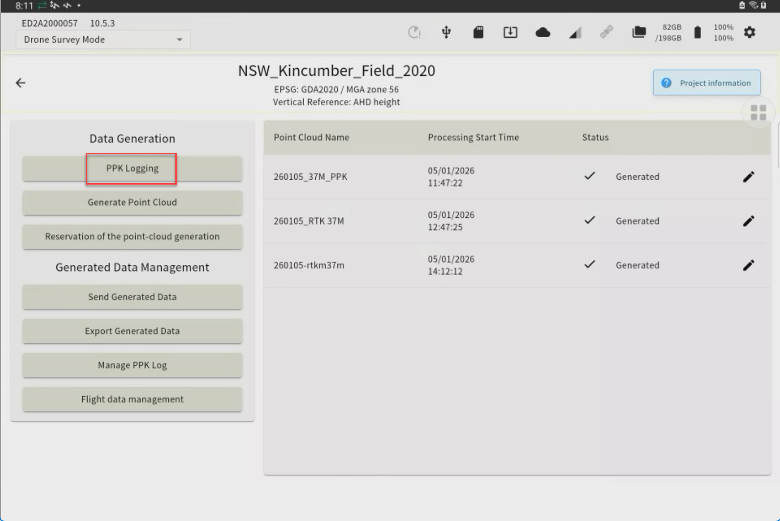
Tap “PPK Logging”
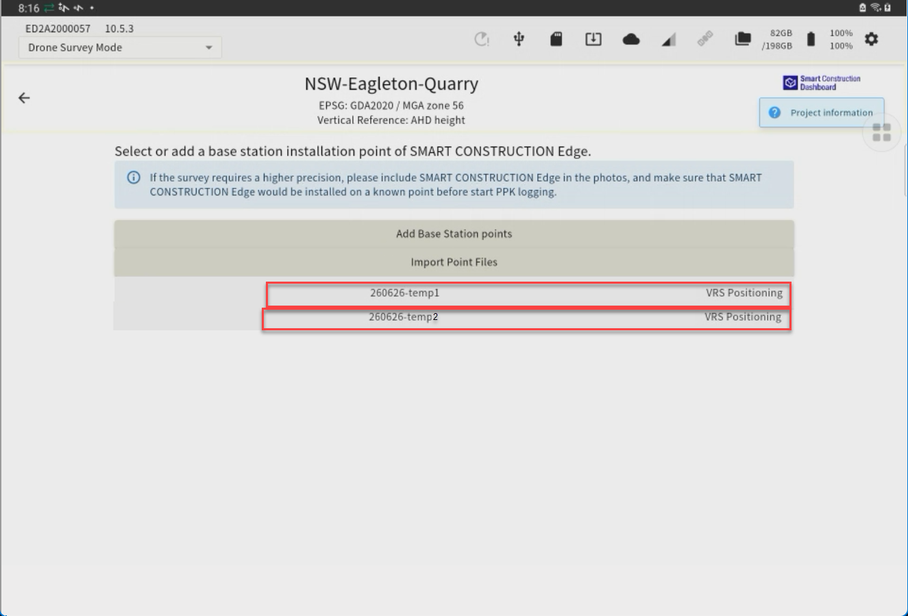
The points you have previously set up or have used for localization will appear as a point list.

If you have set the EdgeBox on one of these points, you can just tap it to select it. (If not, go to 4.)
-
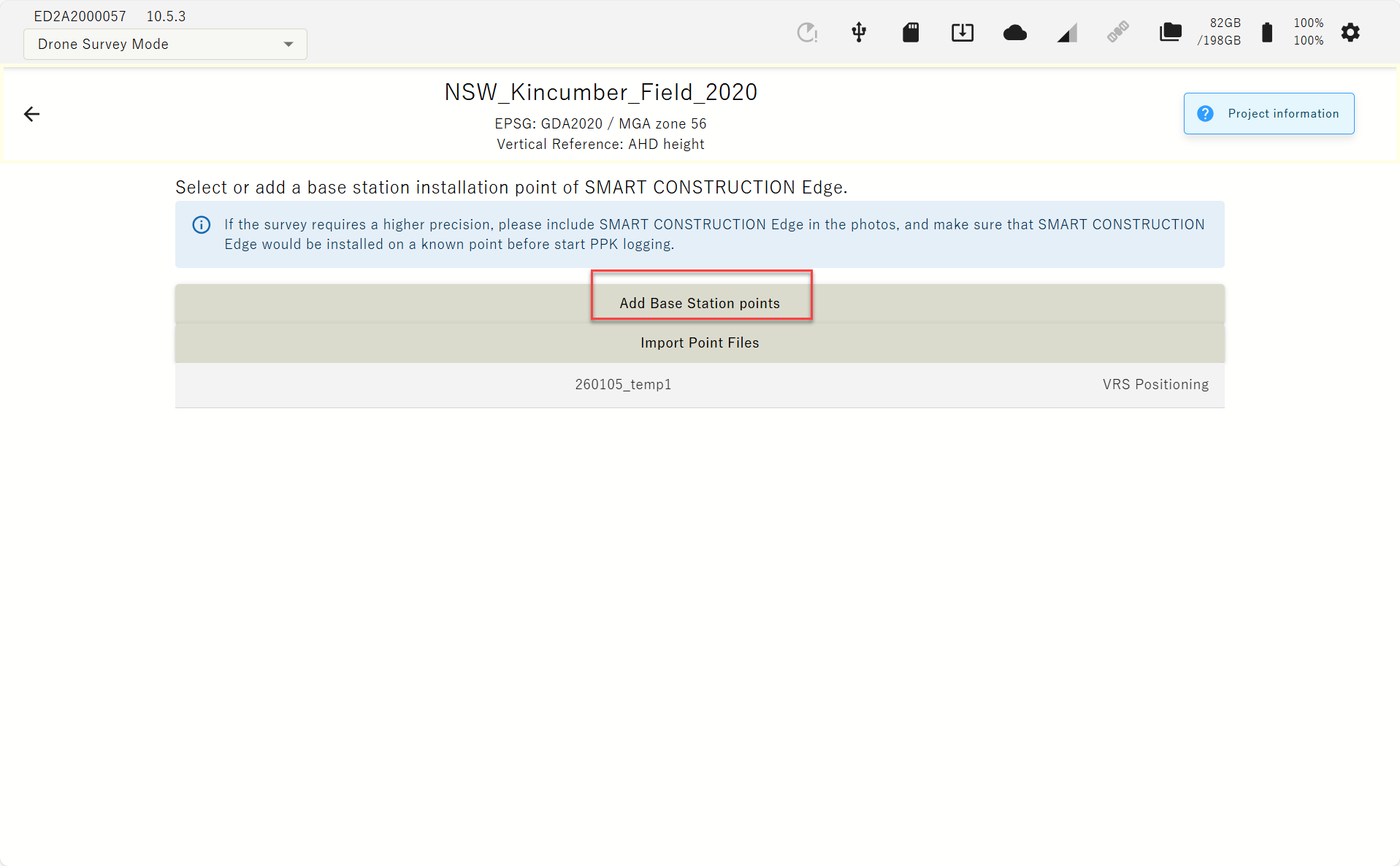
Tap “Adding Installation Points” to Self-Position OR you can import with a CSV file (Go to next chapter.)

-
Enter a point name and tap “Using network RTK” check box
-
Select the network RTK service from the drop-down list and tap the “Execute Positioning” button.
You can set the number of Epoch to measure. See basic settings.
Recommend 60 Epoch
When the positioning is acquired, survey coordinates are automatically entered in the coordinates field.
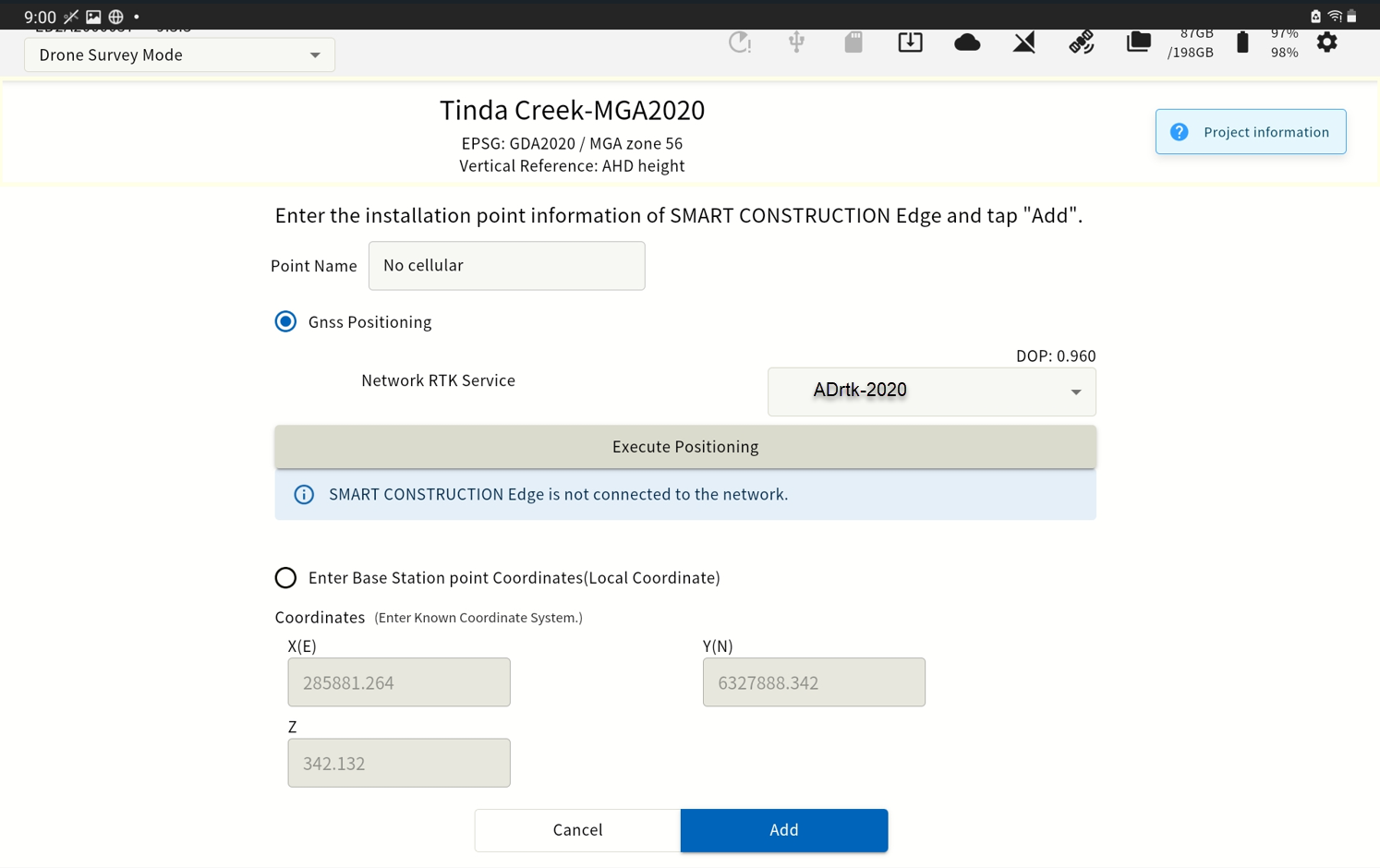
-
Confirm that coordinates are entered in the coordinates field, then tap "Add"
(b) Import from a CSV file
-
Align the Edge Box horizontally above the surveyed control point using a Tribrach & tripod.
-
Measure the height from the base point to the bottom of the EdgeBox
-
Enter this height as the “pole height”

-
Launch the tablet app and select a project of the work site to survey.
If the project is not listed, create a new project.
-
Tap “PPK Logging”
The points you have previously set up or have used for localization will appear as a point list.
-
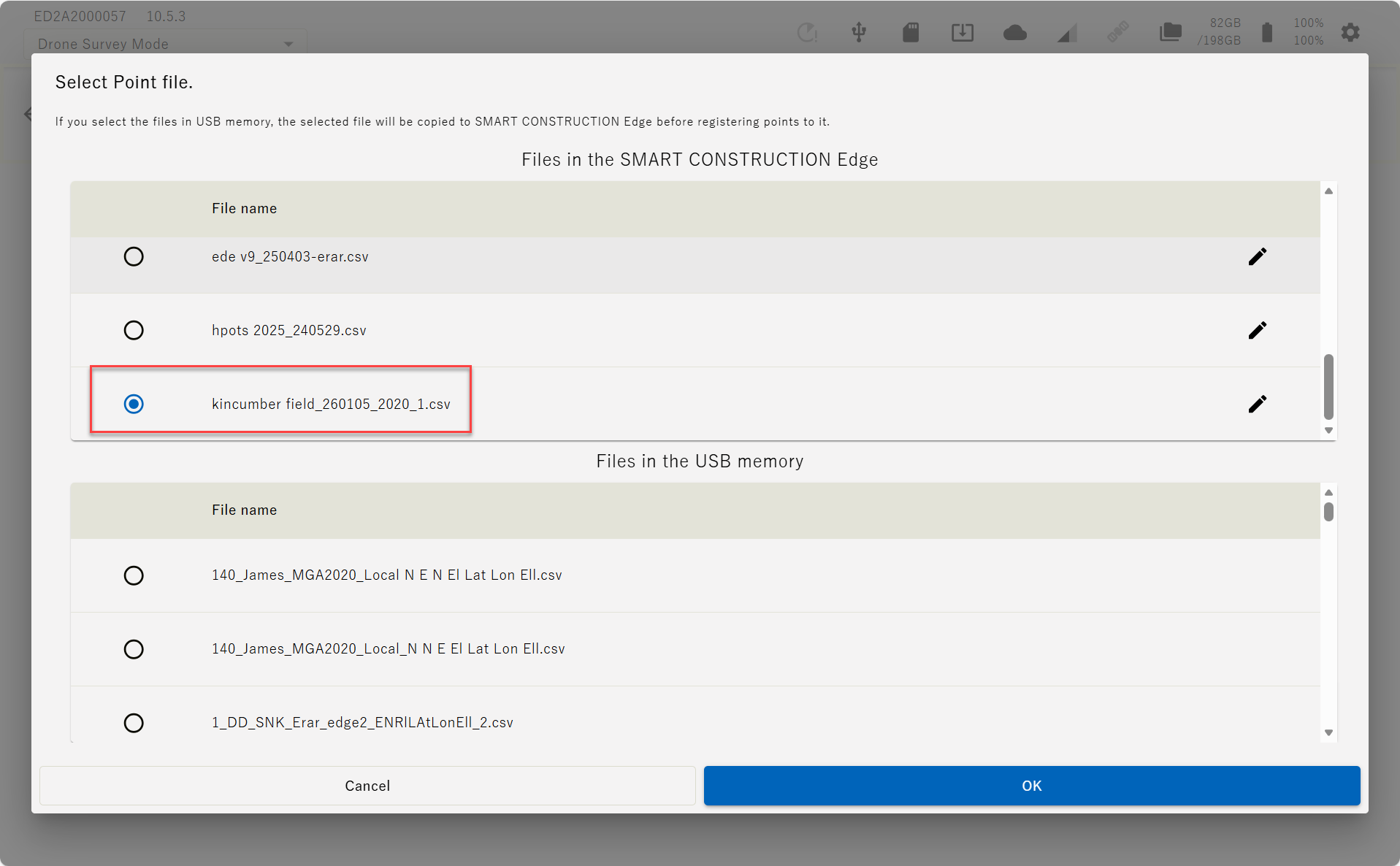
Tap "Import Point Files" to open the file.
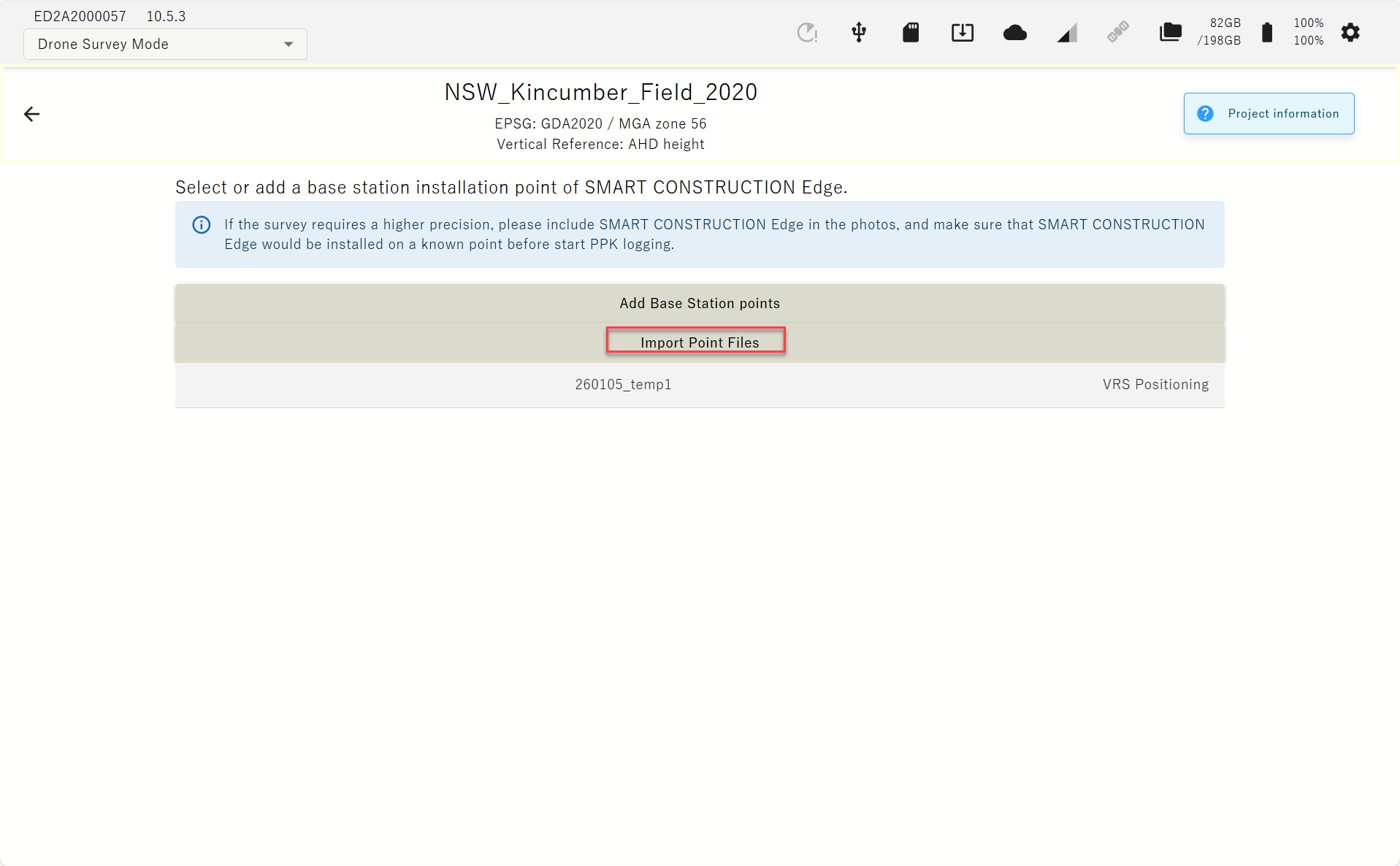
Please prepare the point file in advance.
Select the control point file
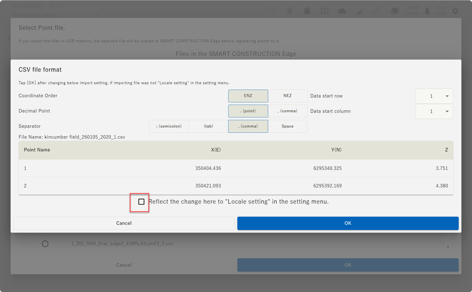
Set the file format parameter according to the file and tap “OK”.
If you tap ”Reflect the change here it ”Locale setting” in the setting menu.” these setting will be reflected to your next settings.
-
The contents of the imported localisation file are displayed on the screen.
Confirm the values are correct and aligned correctly, then tap “OK”.

(c) INPUT manually
-
Align the Edge Box horizontally above the surveyed base point using the levelling device on the top of the tripod.

-
Measure the height from the base point to the bottom of the EdgeBox
-
Enter this height as the “pole height”
-
Launch the tablet app and select a project of the work site to survey.
If the project is not listed, create a new project.
-
Tap “PPK Logging”

-
Tap “Adding Installation Points”.
The points you have previously set up or have used for localization will appear as a point list.
If you have selected one of the point in the list, you may just select it instead of typing in the coordinates.
-
-
Enter the point name and coordinates of the EdgeBox location and tap “Add”.
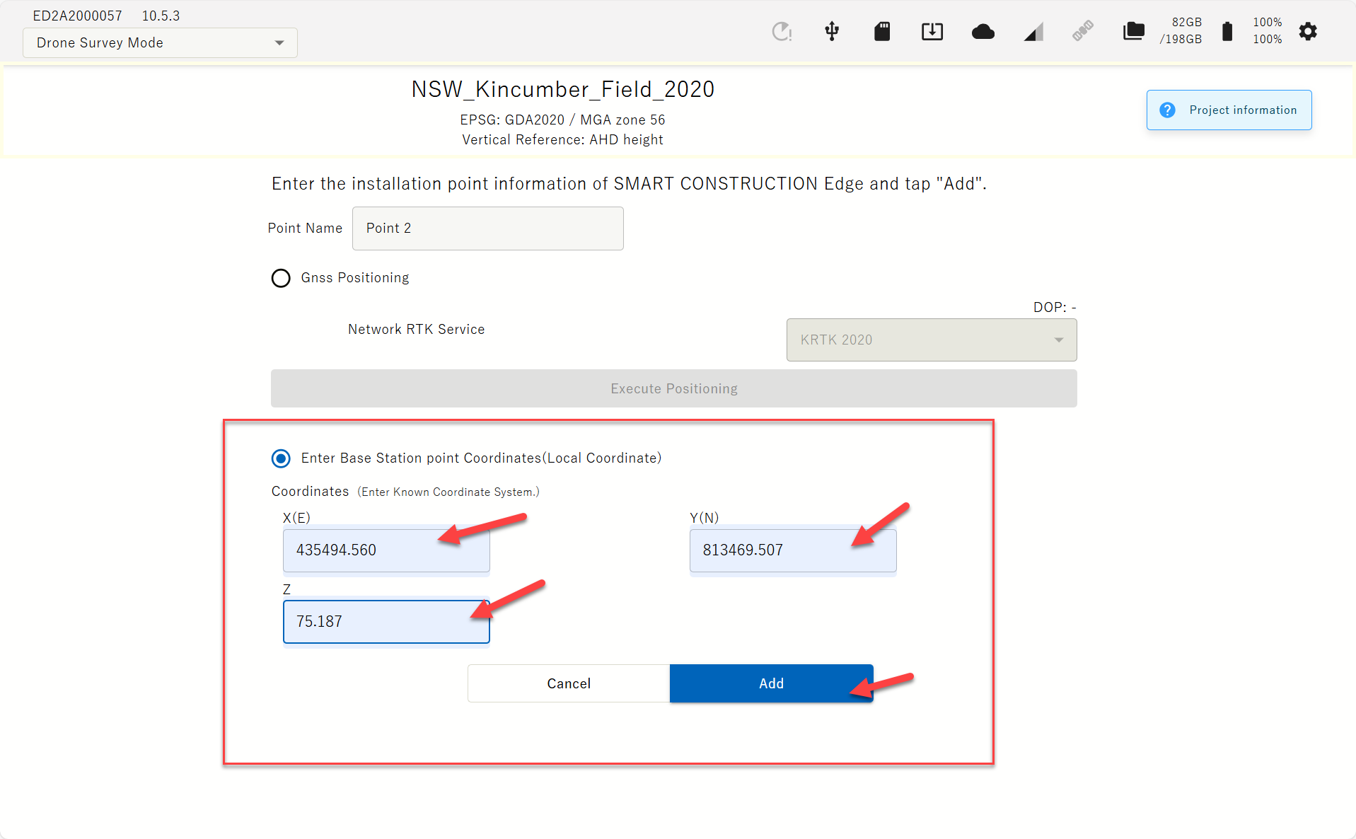
The coordinates you enter must be in the same coordinate system you created the project.
The EDGE2 device must be visible in the Drone images, and it must be set up at a known point during PPK logging as well, for a highly accurate Drone survey.
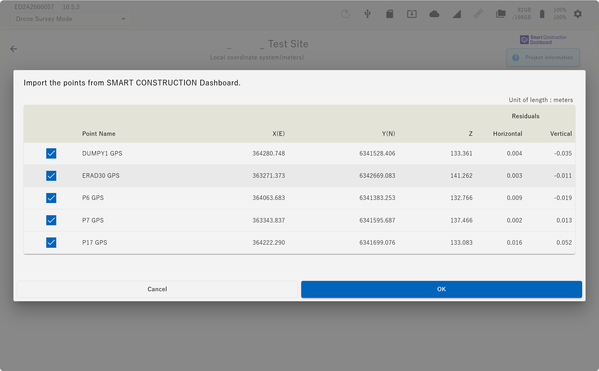
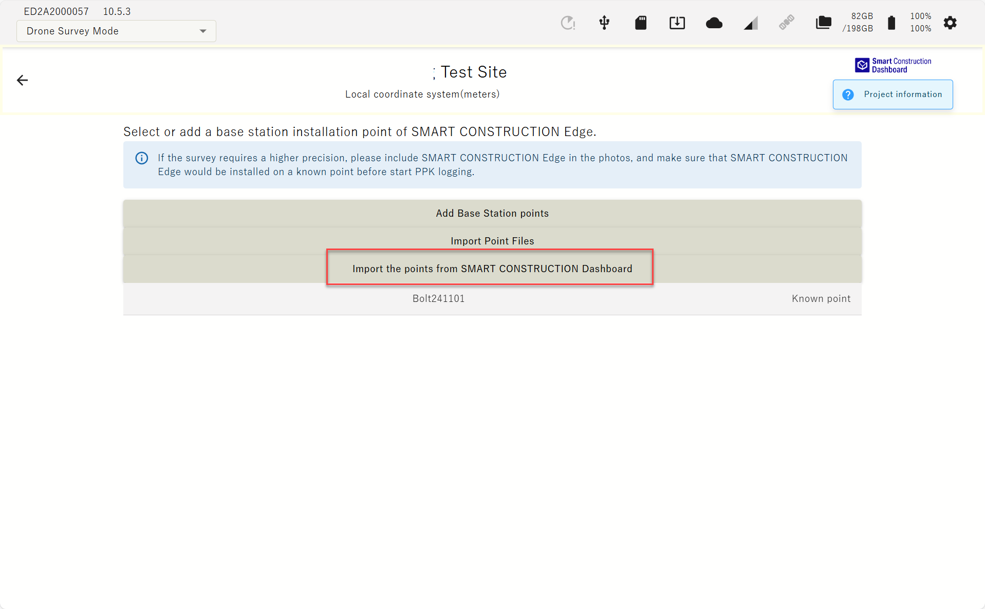
(d) Import from Dashboard
If the project is linked to the Dashboard site, the coordinated data registered on the Dashboard can be imported
Indicated by SC Dashboard Icon top left corner
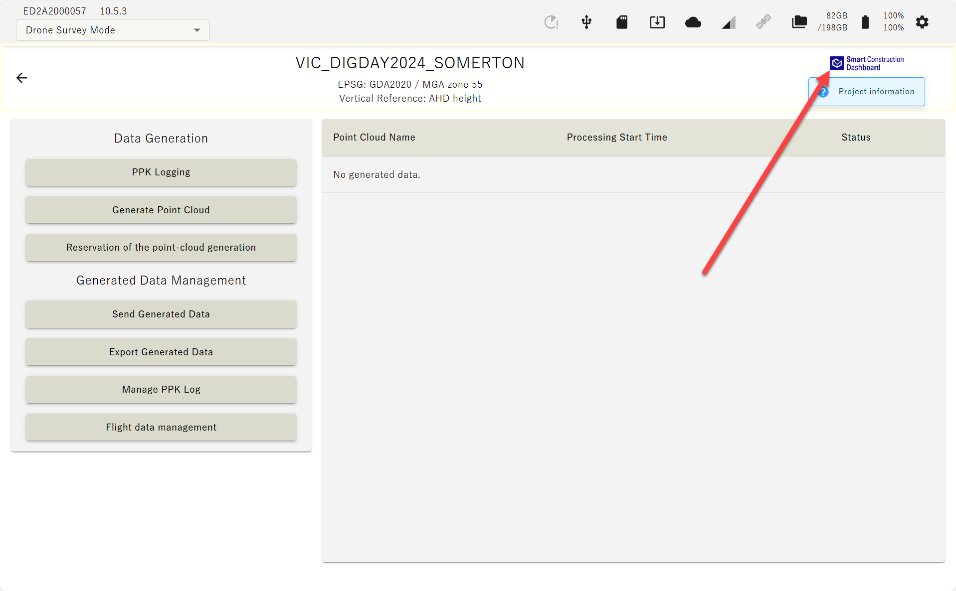
The dashboard icon is displayed for projects linked to the dashboard, and tapping the ‘project information'' icon to view the GC3 information that has been loaded.
-
A list of points registered on the Dashboard is displayed. Select control points and press OK.