
Drone survey function
(a) Using Network RTK to Self-Position
Set Edge to Drone Survey Mode
Before setting the EdgeBox location using Network RTK, you must configure APN settings and Network RTK account settings.
For details, please refer below.
To use Network RTK, an LTE service and a NTRIP Service are required.
-
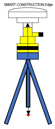
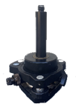
Place EdgeBox on site on a tripod or 5/8 thread bolt with a clear view of the sky.
The main unit should be fixed securely.
Unsecure installation may incur data inaccuracy, error or failure and damage to the Edge.
-
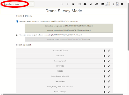
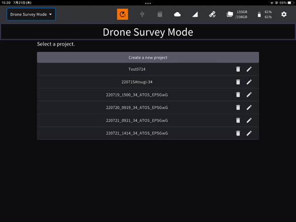
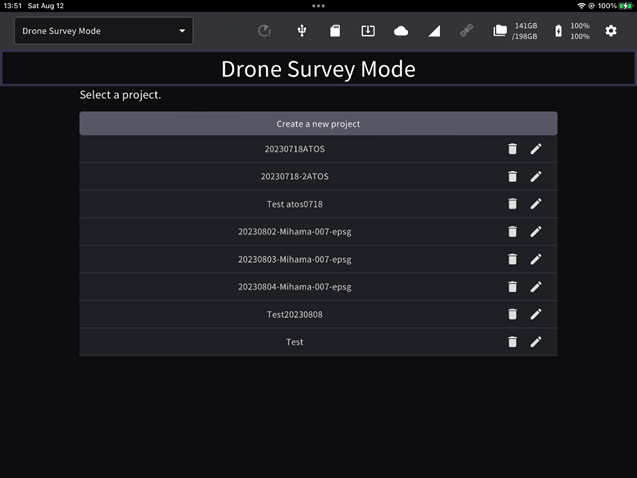
Launch the tablet app and select a project of the work site to survey.
If the project is not listed, create a new project..
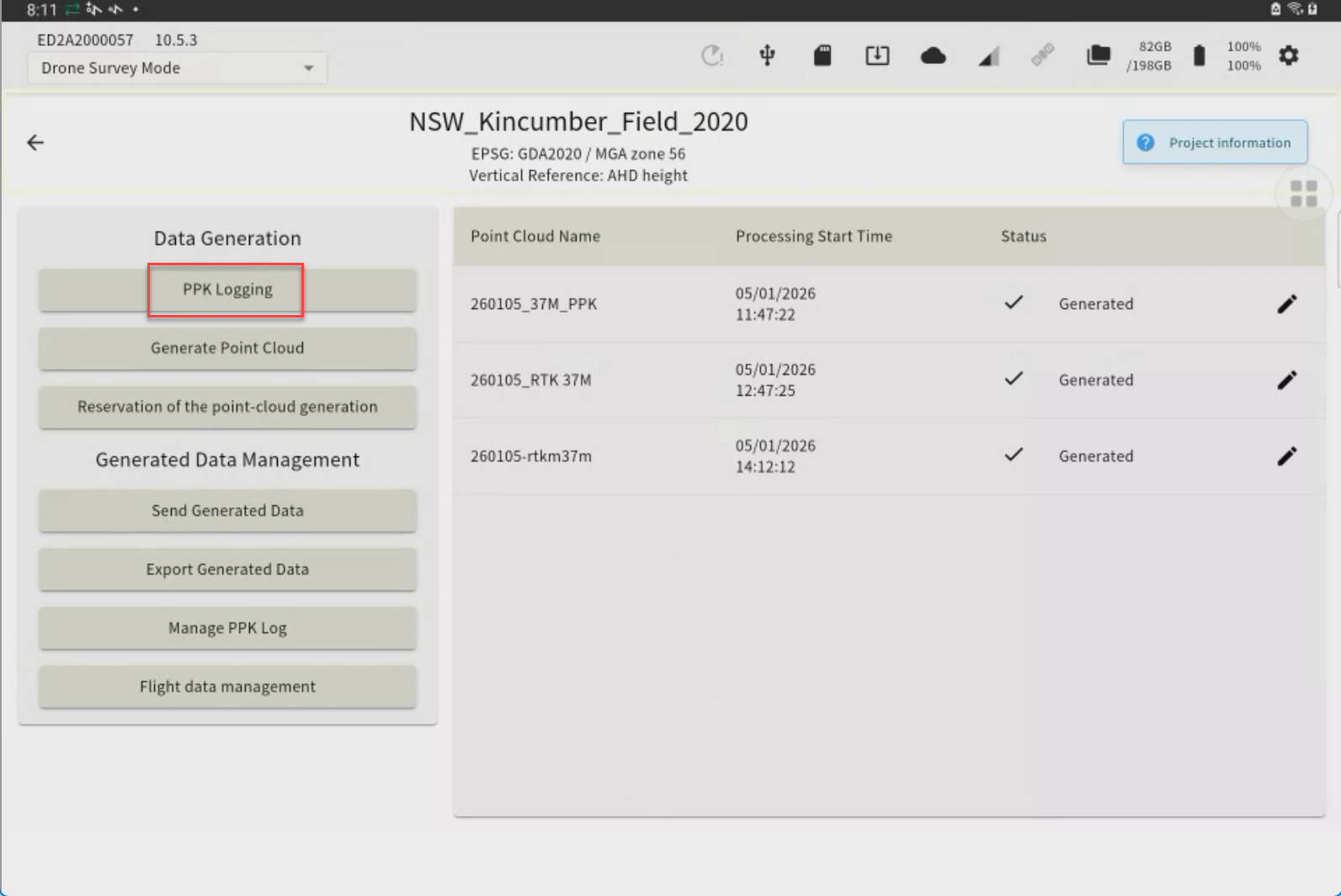
Tap “PPK Logging”
The points you have previously set up or have used for localization will appear as a point list.

If you have set the EdgeBox on one of these points, you can just tap it to select it. (If not, go to 4.)
-
Tap “Adding Installation Points” to Self-Position OR you can import with a CSV file (Go to next chapter.)
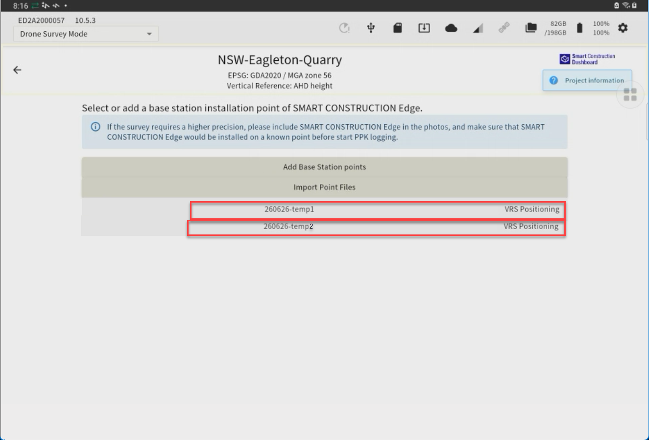
-
Enter a point name and tap “Using network RTK” check box
-
Select the network RTK service from the drop-down list and tap the “Execute Positioning” button.
You can set the number of Epoch to measure. See basic settings.
Recommend 60 Epoch
When the positioning is acquired, survey coordinates are automatically entered in the coordinates field.
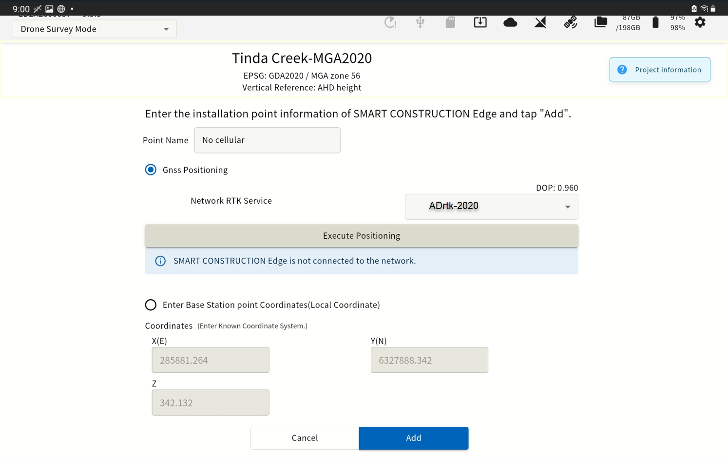
-
Confirm that coordinates are entered in the coordinates field, then tap "Add"
(b) Import from a CSV file

-
Align the Edge Box horizontally above the surveyed control point using a Tribrach & tripod.
-
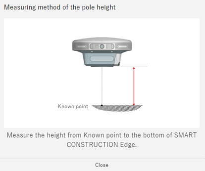
Measure the height from the base point to the bottom of the EdgeBox
-
Enter this height as the “pole height”
-
Launch the tablet app and select a project of the work site to survey.
If the project is not listed, create a new project.
-
Tap “PPK Logging”

The points you have previously set up or have used for localization will appear as a point list.
-
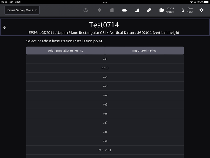
Tap "Import Point Files" to open the file.
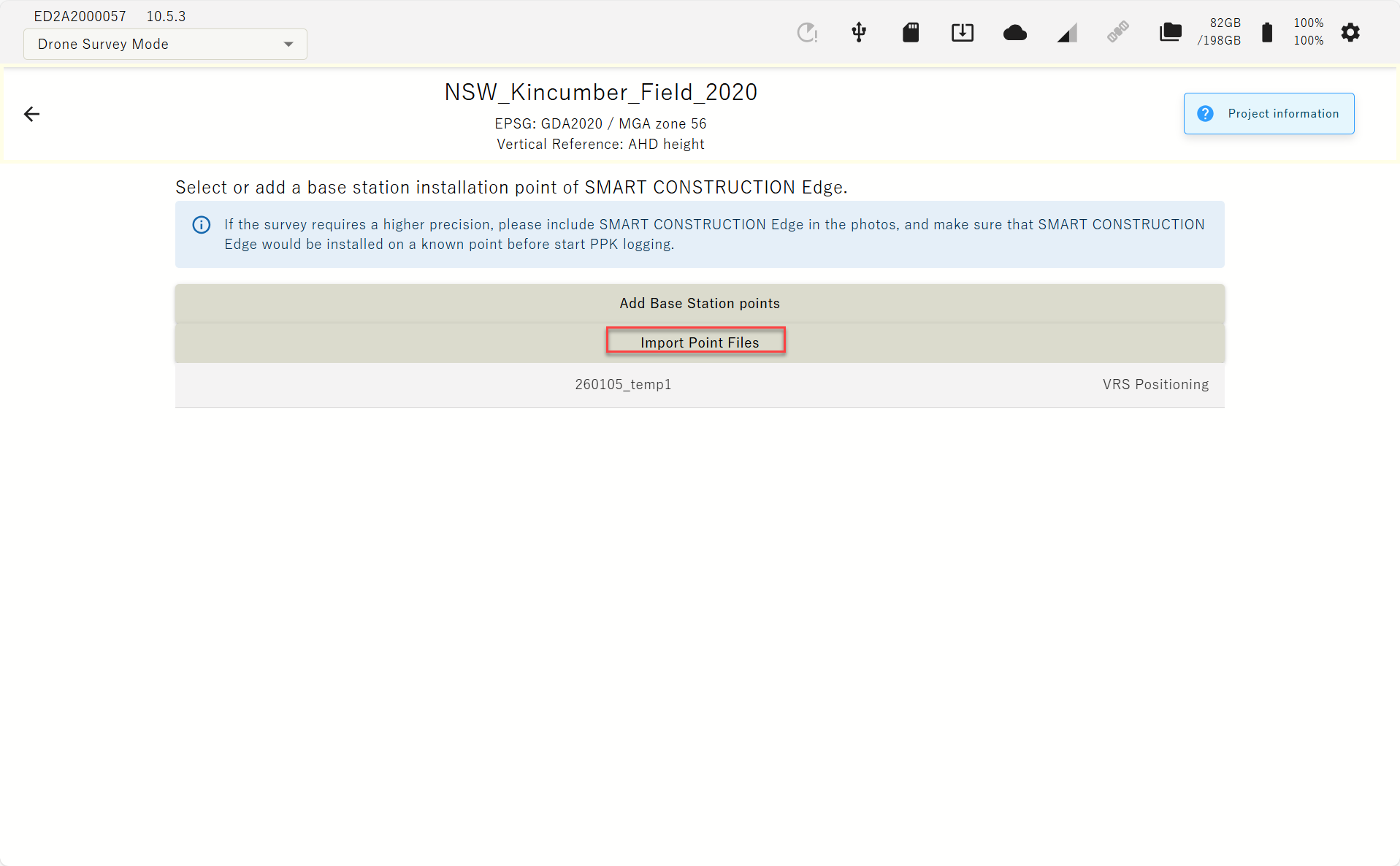
Please prepare the point file in advance.
Select the control point file
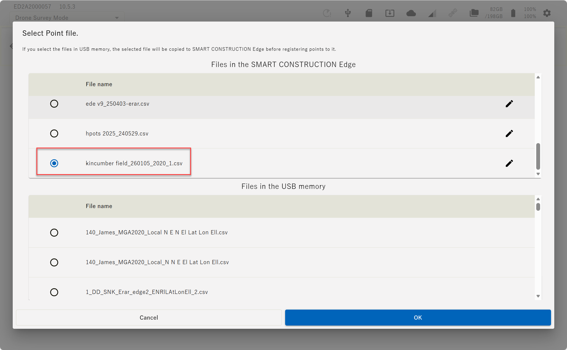
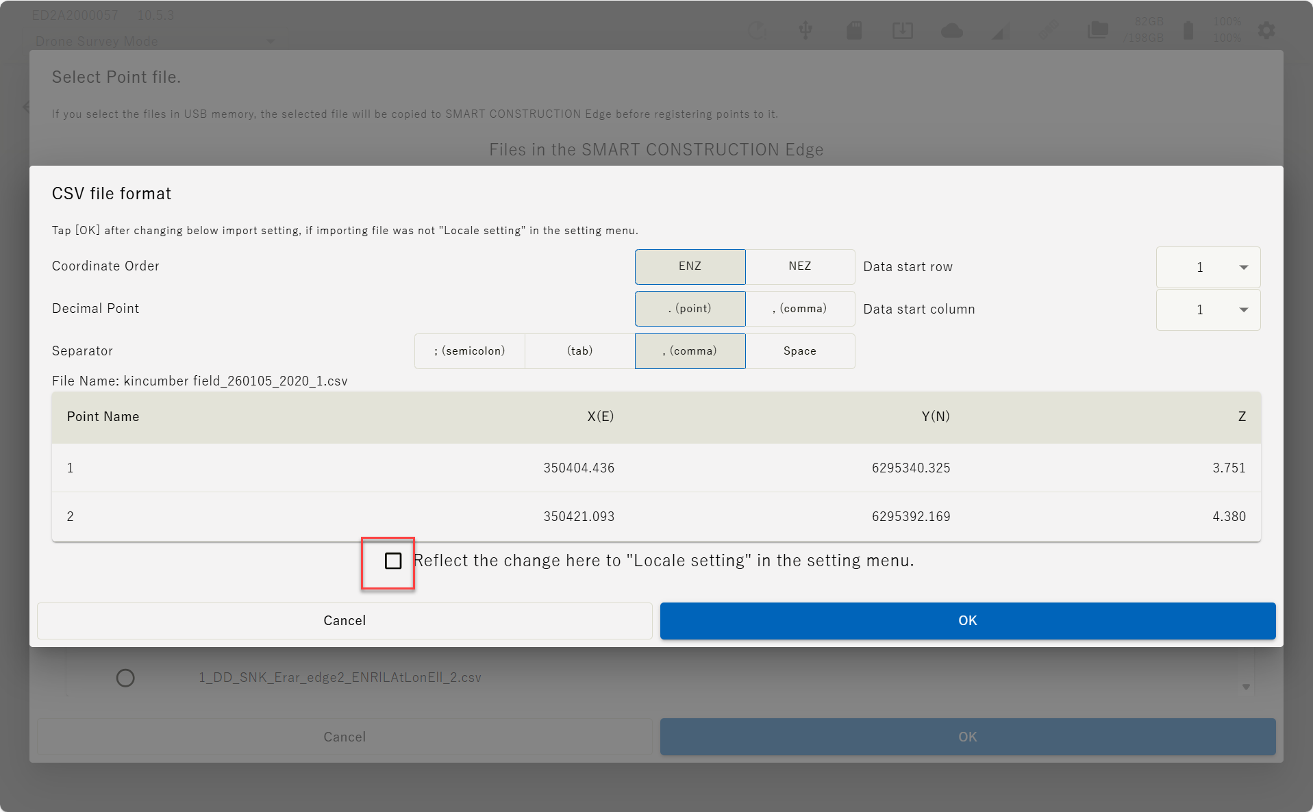
Set the file format parameter according to the file and tap “OK”.
If you tap ”Reflect the change here it ”Locale setting” in the setting menu.” these setting will be reflected to your next settings.
-
The contents of the imported localisation file are displayed on the screen.
Confirm the values are correct and aligned correctly, then tap “OK”.
(c) INPUT manually
-
Align the Edge Box horizontally above the surveyed base point using the levelling device on the top of the tripod.
-
Measure the height from the base point to the bottom of the EdgeBox
-
Enter this height as the “pole height”

-
Launch the tablet app and select a project of the work site to survey.
If the project is not listed, create a new project.
-
Tap “PPK Logging”
-
Tap “Adding Installation Points”.
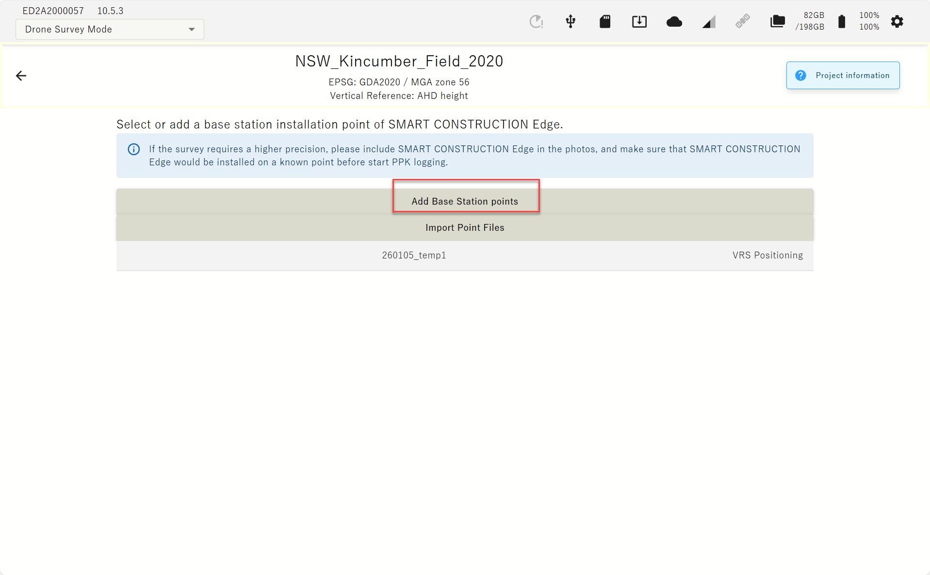
The points you have previously set up or have used for localization will appear as a point list.
If you have selected one of the point in the list, you may just select it instead of typing in the coordinates.
-

-
Enter the point name and coordinates of the EdgeBox location and tap “Add”.
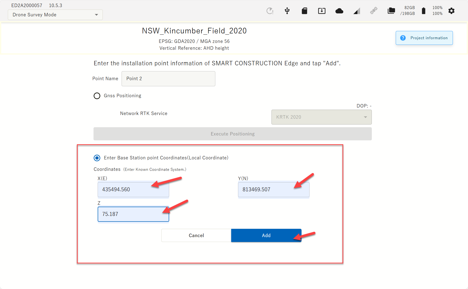
The coordinates you enter must be in the same coordinate system you created the project.
The EDGE2 device must be visible in the Drone images, and it must be set up at a known point during PPK logging as well, for a highly accurate Drone survey.
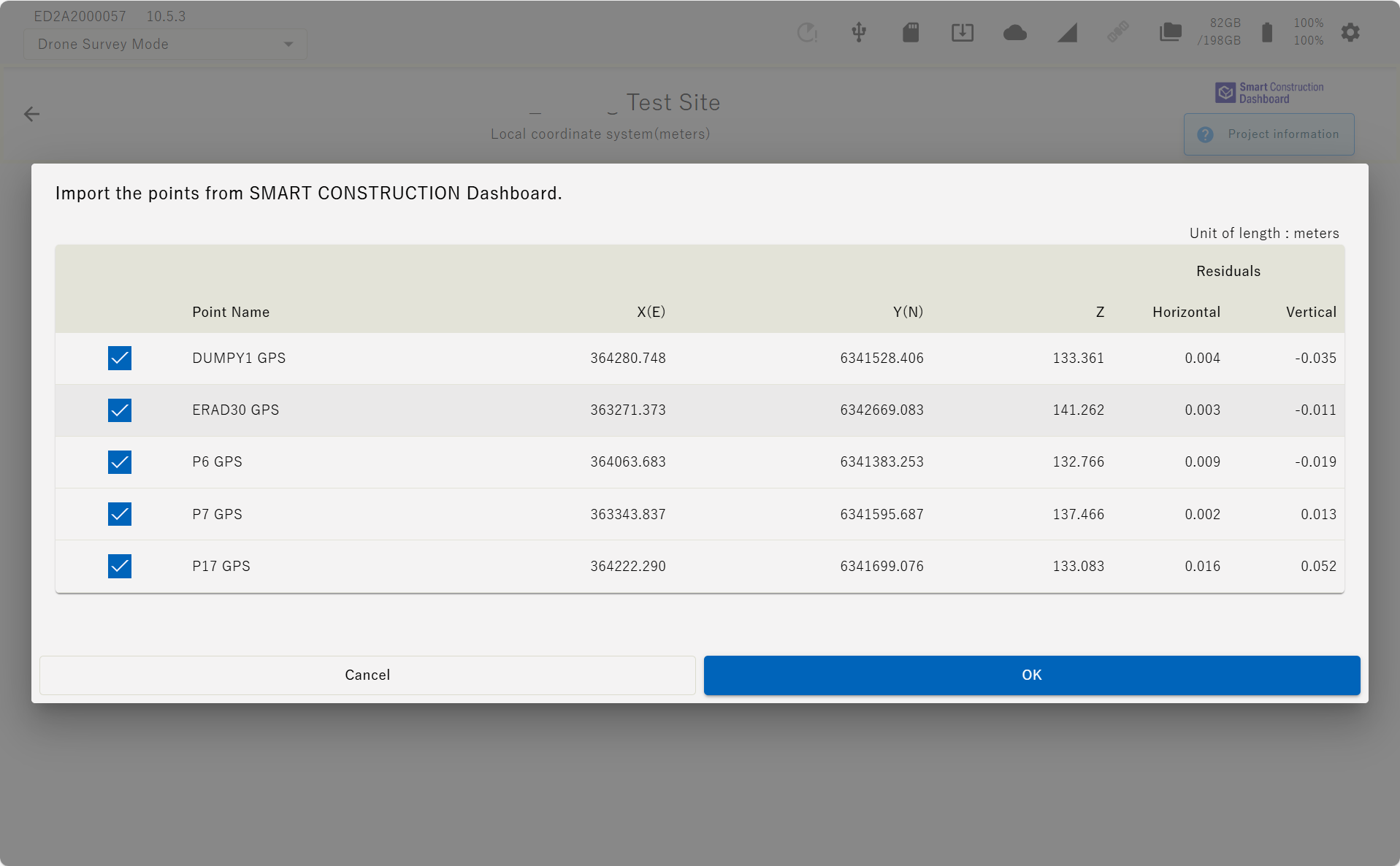
(d) Import form Dashboard
If the project is linked to the Dashboard site, the coordinated data registered on the Dashboard can be imported
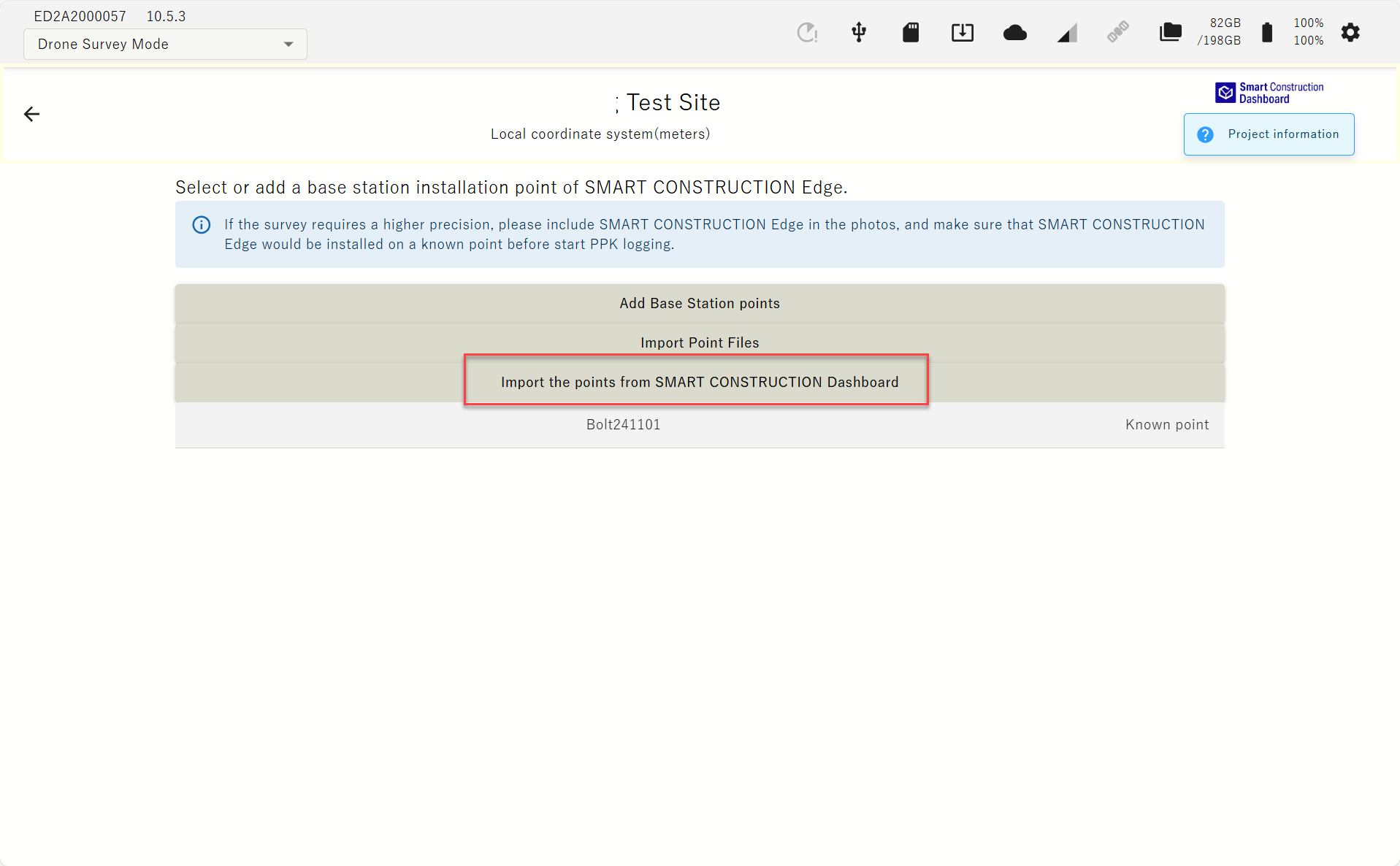
Indicated by SC Dashboard Icon top left corner
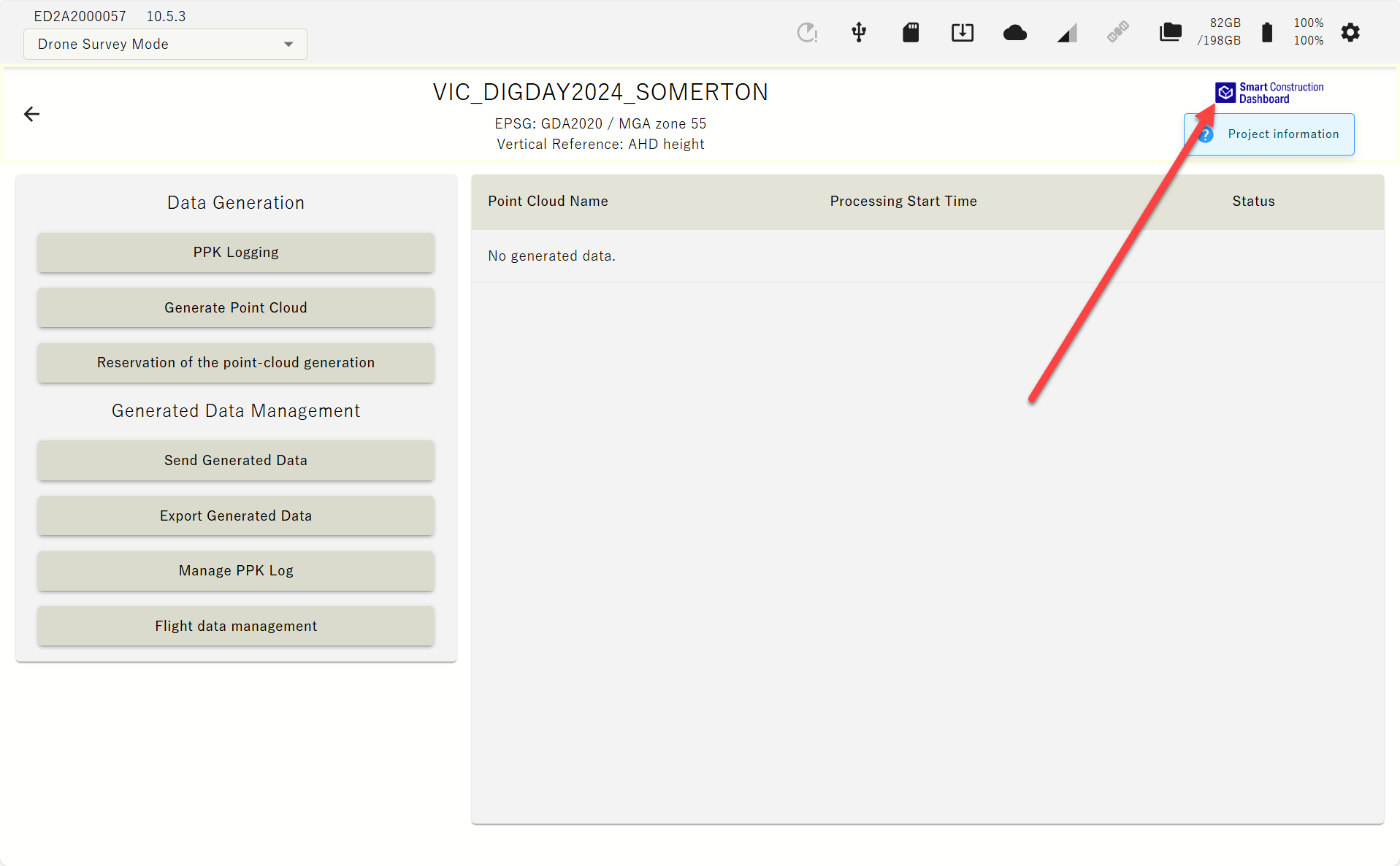
The dashboard icon is displayed for projects linked to the dashboard, and tapping the ‘project information'' icon to view the GC3 information that has been loaded.
-
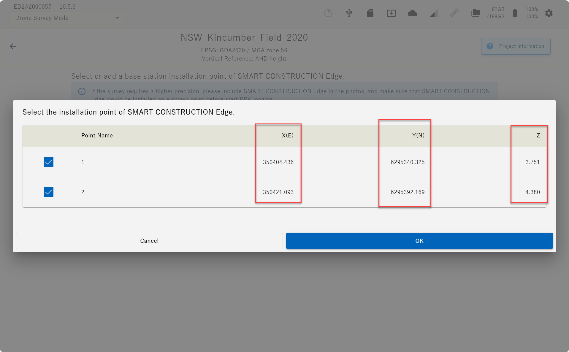
A list of points registered on the Dashboard is displayed. Select control points and press OK.
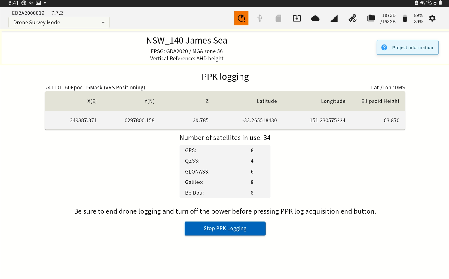
Start PPK logging
-
Select the point of EdgeBox from the point list.
-
Check the point data and the number of satellites used and tap the "Start PPK Logging" button.
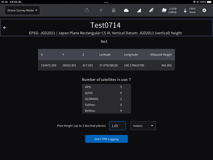
If you have set points manually or imported from a localisation file, you need to enter a pole height in advance.
Make sure that the PPK logging has started before you start flying the drone.
Wait 3 min. to stabilize GNSS reception after starting PPK logging and then, 2 min. after turning on the drone.
End PPK logging
Make sure that your drone has completed its flight and that the drone and controller are powered off before you end PPK logging. This may adversely affect the accuracy of the PPK.
-
Tap the "PPK Logging Complete" button.
-
If GNSS reception deteriorates during the logging period, an error message may be displayed.
Please note that this may affect the accuracy of the PPK.
Generating Point Clouds
-
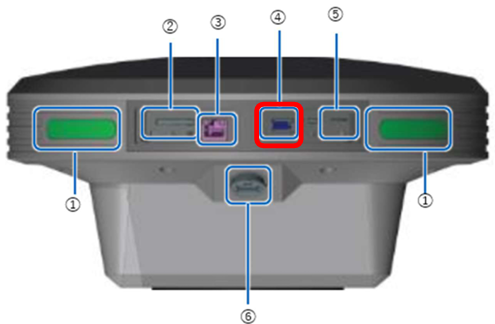
After flying the drone, insert the SD card containing photo data from the drone into the SD card slot of the EdgeBox.
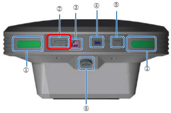
① Status LED
② SD card slot
③ Ether cable port
④ USB slot(USB3.0)
⑤ SIM card slot
⑥ Water-proof USB slot(USB2.0)
Before inserting the SD card, please check the direction and insert straightly. If you force to insert, may damage SD card or this product.
If insert wrongly and cannot take out the SD card, please contact Smart Construction Helpdesk. Please do not take out the SD card by inserting tweezers and so on, you may damage the product by short circuit.
-
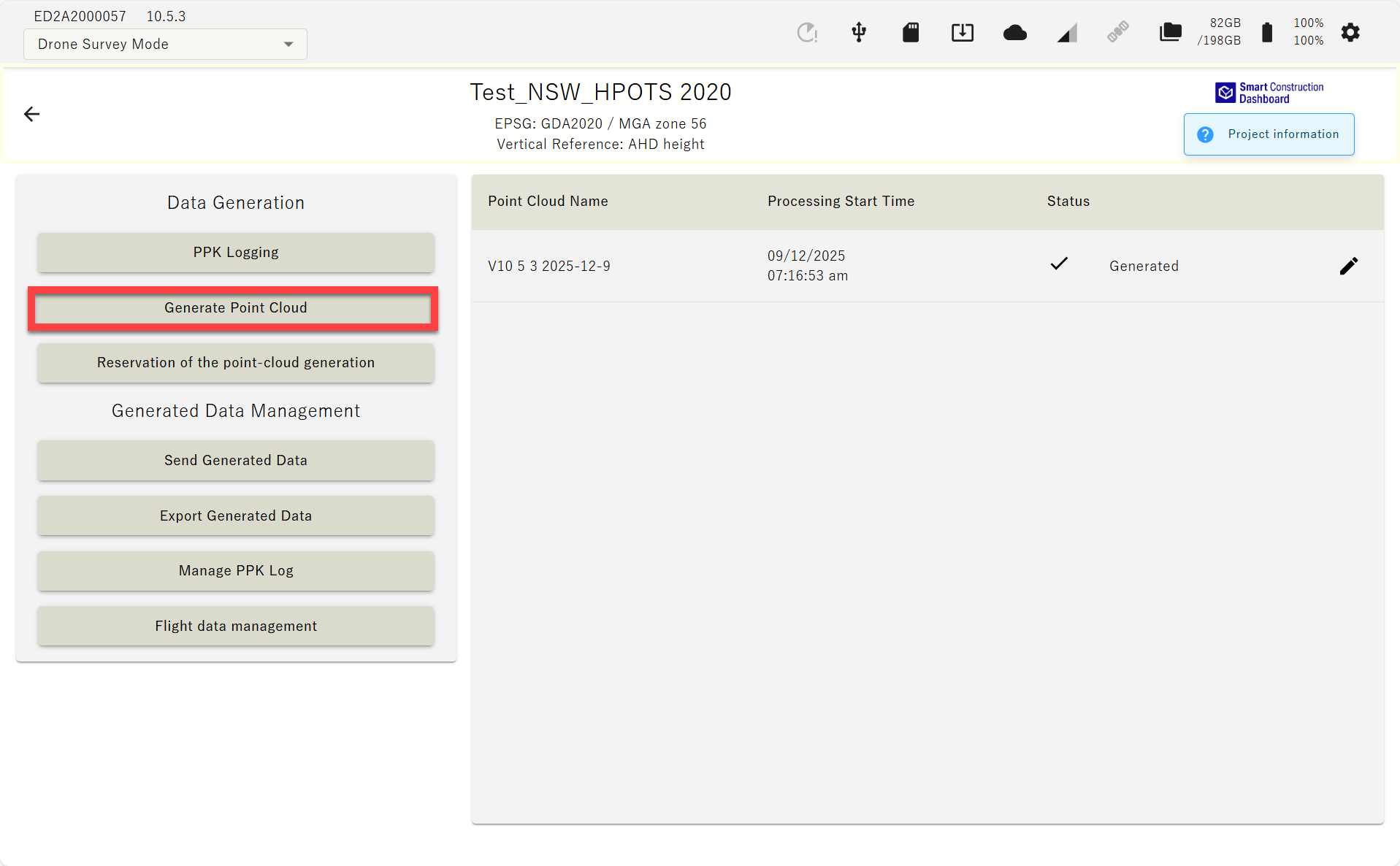
Tap the “Point Cloud Generation” button on the top screen of the project.
-
Enter the point cloud name and press OK.
Make sure that “Use PPK Only” is selected.
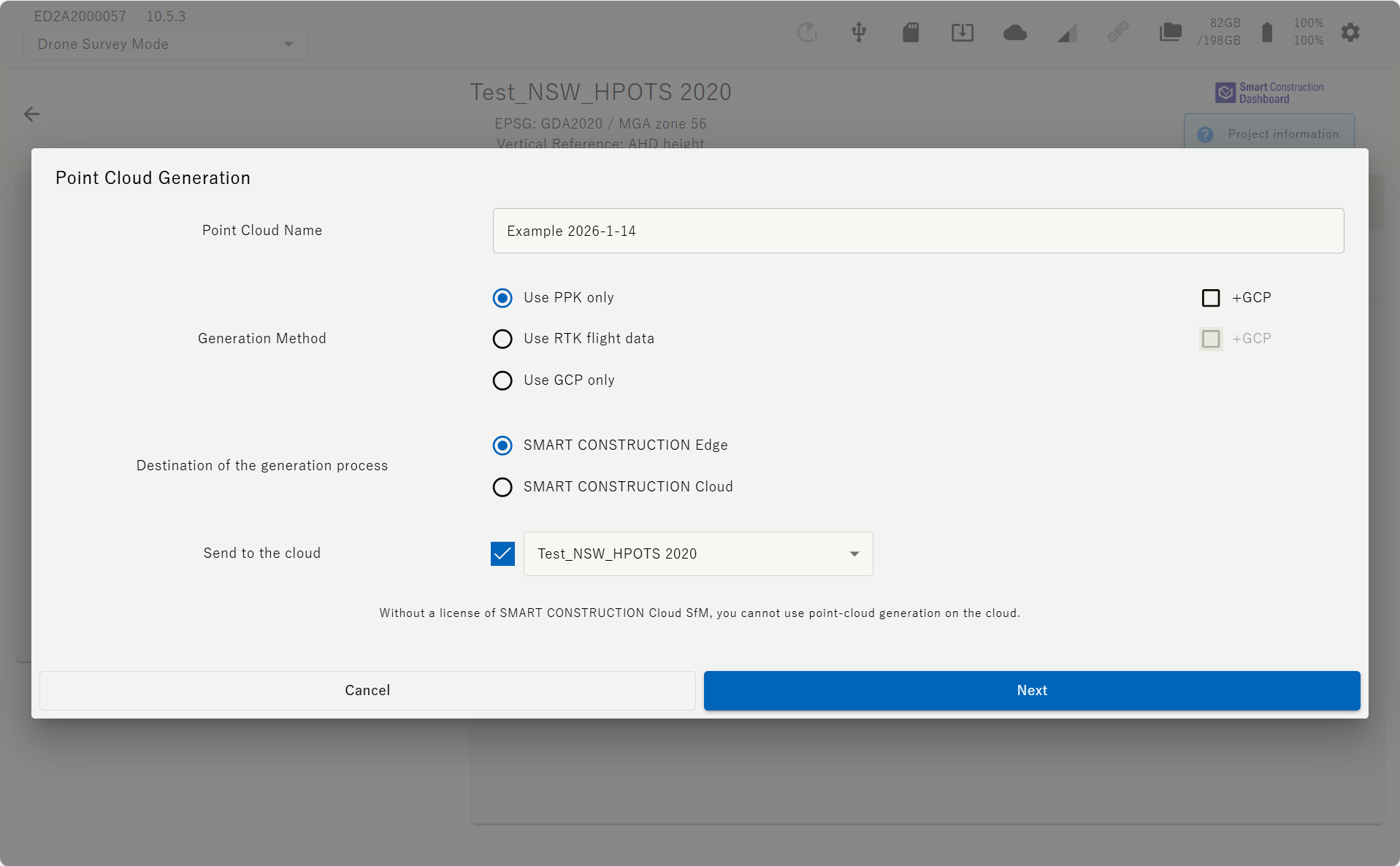
You can also improve the point cloud accuracy by using GCPs.
Using RTK flight data will be the same except the PPK data processing process.
Destination of the generation process. “SMART CONSTRUCTION Edge” to process onboard the Edge device.
Destination of the generation process’s. SMART CONSTRUCTION Cloud to send the unprocessed drone data(photos) via Edge to SC Cloud SfM for processing. This will require SfM Credits for processing.
Send to the cloud. Select the SC Dashboard project tot automatically send the processed data once completed to the Dashboard via the Edge cellular.
Reservation of the point Cloud can automated processing from PPK to Upload-to-Dashboard without manual intervention. ''Reservation of the point Cloud ‘is not available GCP processing.
-
Tap the "Import Flight Data" button and select the drone data to upload to the EdgeBox from the displayed dialog. Flight data can be imported from SD or USB.
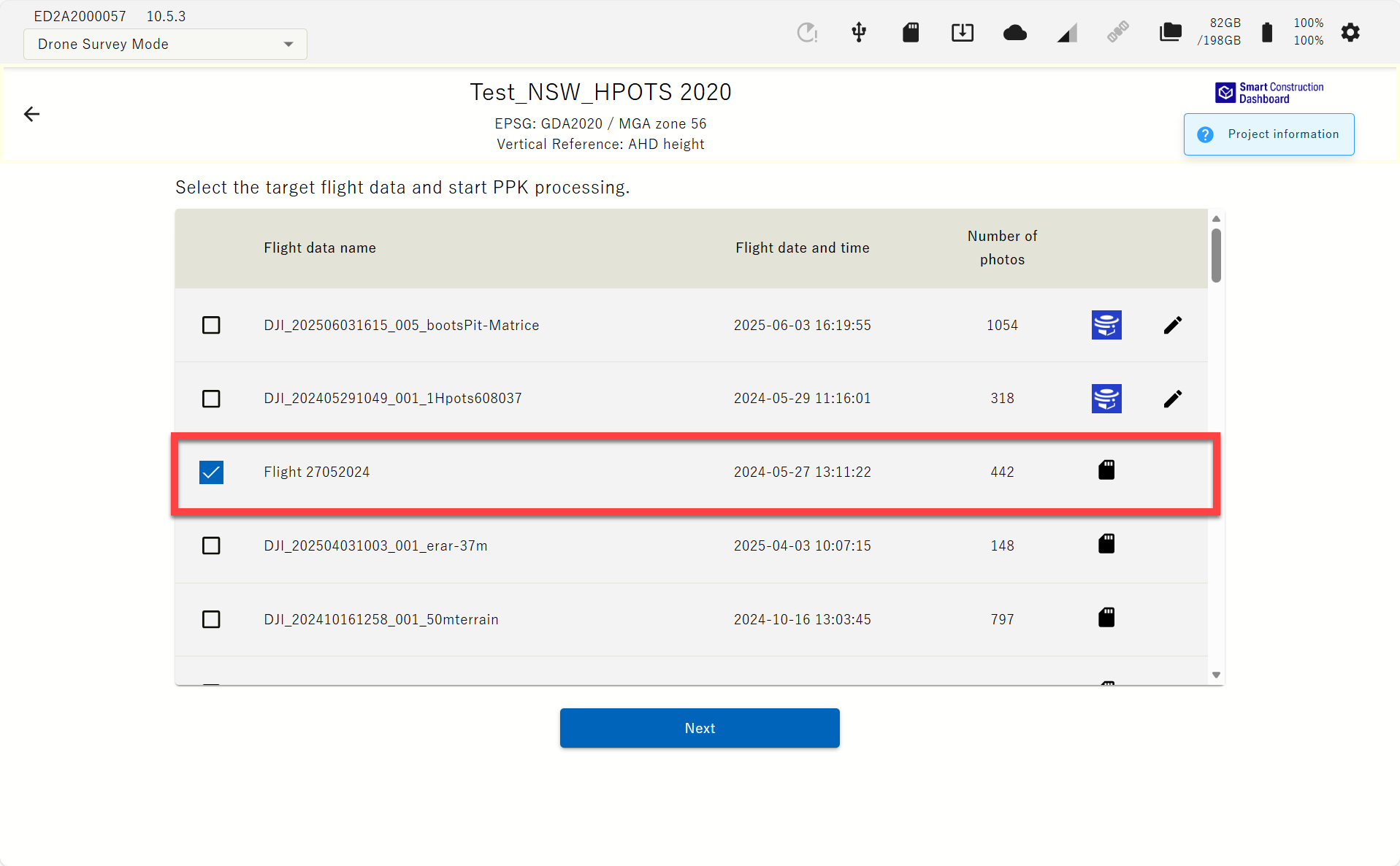
"If Edge 2 cannot be included in the drone photo, a GCP marker can be used to improve the accuracy of the point cloud. When Edge 2 is included in the drone photo, it serves as a GCP, allowing high accuracy with PPK-only processing."
The imported data will be listed. You can also select and import multiple data.
-
Check the flight data to generate point cloud from the imported data list and tap " Start PPK processing" button.
See details bellow of the recommended settings.
Point Cloud delivers rapid 3D data for volume calculations only. Use it when quick data turnaround is needed. Selecting Orthophoto increases processing time.
※If you tap ''Conditions which was able to generate point cloud'' The number of photos loaded and the maximum number of photos processed at each density can be checked.
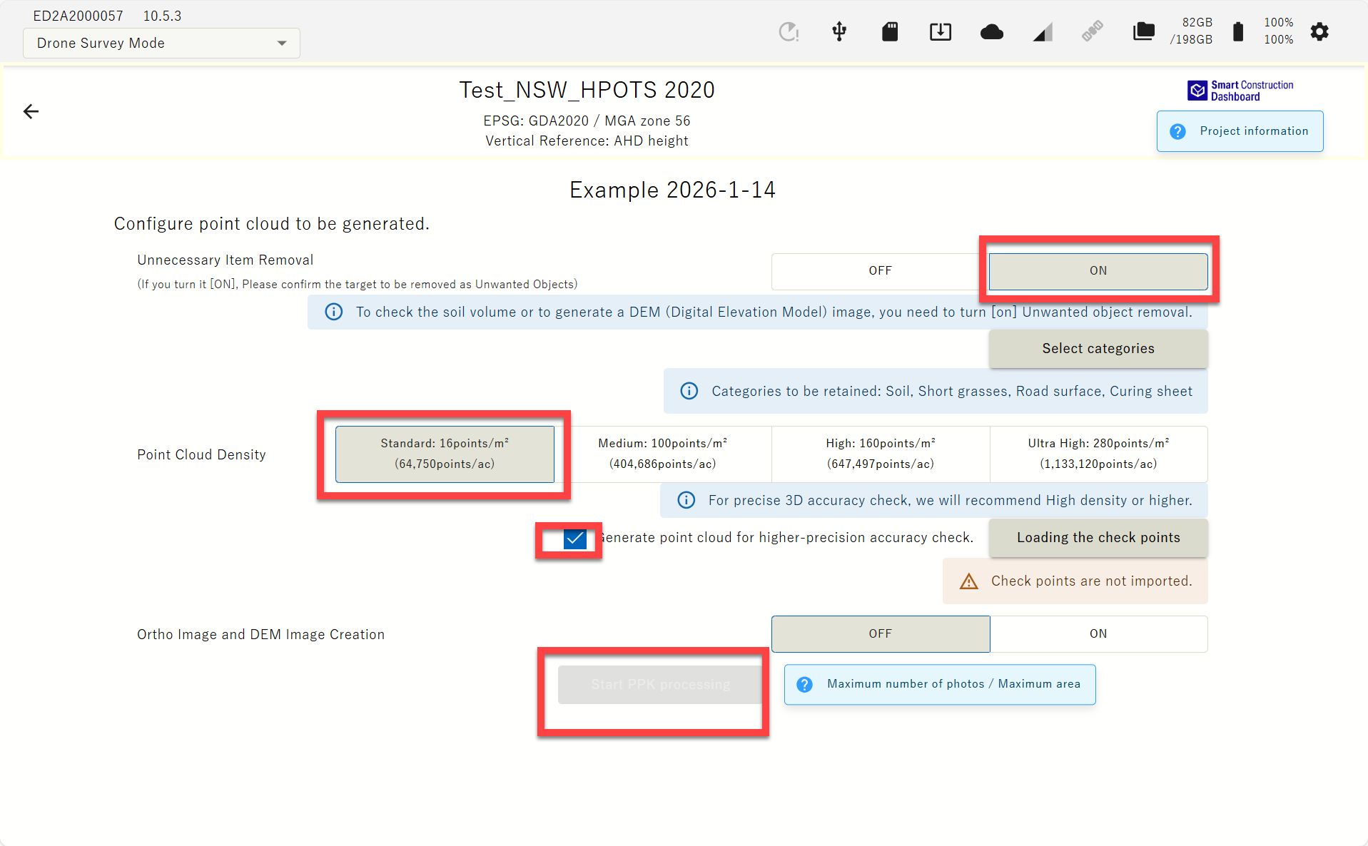
Tick on “ Generate point cloud for higher-precision accuracy check” before generating point cloud. This increases the point cloud density in the vicinity of the Check Points.
Unnecessary object Removal:
When you toggle ON, it removes unnecessary objects, such as buildings and vehicles, that are not needed for soil volume calculations.
Press “Select Category” to choose the category for removal or to retain.
It is recommended to Retain all objects.
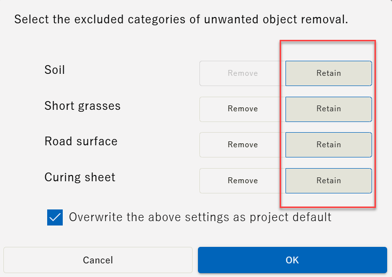
“Short grasses" can remove/retain all Short grasses, other vegetation such as tall trees will be removed, and "Road Surface" can remove/retain road surfaces, including concrete. The “curing sheet” could remove/retain a green or blue sheet on site.
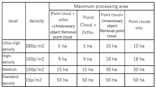
Point Cloud Density :Adjusts the density of the point cloud
3D accuracy check requires Ultra high density. There’s area size limitation with this setting setout in the table below.
|
level |
density |
Maximum processing area |
|||
|
Point cloud + ortho +Unnecessary object Removal point cloud |
Point Cloud + Ortho |
Point cloud+ Unnecessary object Removal point cloud |
Point clouds only |
||
|
Ultra-high density |
280p/m2 |
5 ha |
5 ha |
10 ha |
10 ha |
|
High-density |
100p/m2 |
15 ha |
15 ha |
30 ha |
30 ha |
|
Standard density |
16p/m2 |
50 ha |
50 ha |
50 ha |
50 ha |
Ortho and DEM image generation:
Generate ortho (sky photo) and DEM (Digital Elevation Model).
If you do not turn on ortho generation, you will not be able to output an image showing the verification point positions on the ortho, which is the 3D accuracy check report material.
-
A dialog showing the PPK Fix rate will appear, check the rate and press "Generation Start".
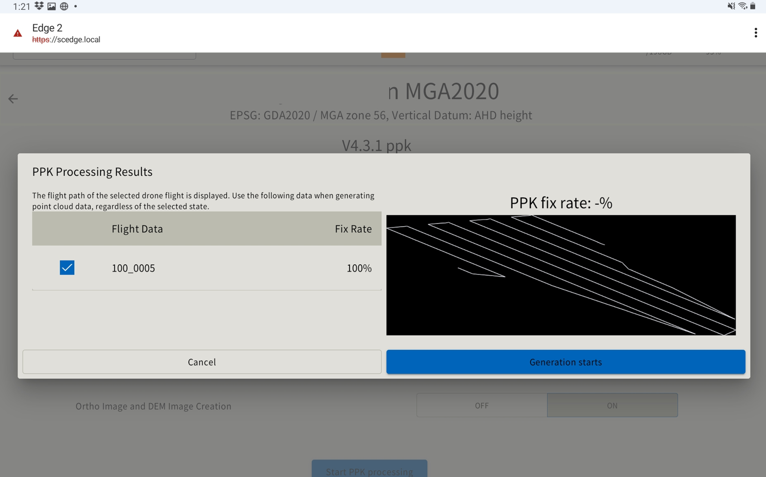
A low PPK Fix rate may affect the accuracy of the resulting point cloud. At the point where the red × mark on the drone flight route has a worse acquisition of the drone location. Please confirm and fly again if necessary.
-
The point cloud viewer screen shows up and the point cloud generation process starts. During this process, it is possible to switch to another window and perform the other work. You can check the generated point cloud by selecting it from the list on the project top screen.
To generate a Digital Elevation Model (DEM), both the Unwanted Object Analysis and Ortho Image Generation settings must be both ON.
If you turn off SMART CONSTRUCTION Edge during the processes below, the data could be corrupted, or the system doesn’t work properly any more.
Please turn off after these processes are done.
・Point cloud generation
・PPK logging
・Point cloud uploading
・Data exporting
WHEN WE USE GCPS TO IMPROVE THE ACCURACY
If Edge 2 cannot be included in the drone photo, a GCP marker can be used to improve the accuracy of the point cloud. When Edge 2 is included in the drone photo, it serves as a GCP, allowing high accuracy with PPK-only processing. Please prepare the drone image with GCPs and coordinate information of GCP.
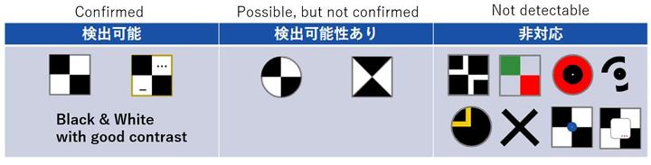
In v10, when performing SFM processing using GCPs, the positions of the following markers can now be automatically detected.
Detectable markers
-
Select "Use PPK and GCP" in step 4 of "Generating Point Clouds".

-
Tap the "Import Flight Data" button and select the drone data to upload to the EdgeBox from the displayed dialog.
-
The imported data will be listed. You can also select and multiple imported data.
-
Check the flight data to generate point cloud from the imported data list and tap "PPK processing start" button.
※If you want to automatically upload the point cloud, check (Send to cloud) and select the upload destination.
-
A dialog showing the PPK Fix rate will appear, check the rate and press "Next"
A low PPK Fix rate may affect the accuracy of the resulting point cloud. At the point where the red × mark on the drone flight route has a worse acquisition of the drone location. Please confirm and fly again if necessary.
-
Check the flight data to generate point cloud from the imported data list and tap " Start PPK processing" button.
“Use GCP only” This is a preliminary functional update based on future updates and will enable GCP-only SFM processing for P4RTK, M3E, and M300. We have confirmed the accuracy, but if there is no need for GCP-only processing, we recommend normal PPK/RTK or +GCP processing for the models listed above at this time.
-
We will show the details of the setting items from the next page.

-
※If you tap ''Conditions which was able to generate point cloud'' The number of photos loaded and the maximum number of photos processed at each density can be checked.
Unnecessary object removal: When you toggle ON, it removes unnecessary objects, such as buildings and vehicles, that are not needed for soil volume calculations. Press “Select Category” to choose the category for removal.
“Short grasses" can remove/retain all Short grasses, other vegetation such as tall trees will be removed and "Road Surface" can remove/retain road surfaces, including concrete. The “curing sheet” could remove/retain a green or blue sheet on site.
Point Cloud Density :Adjusts the density of the point cloud Tips 3D accuracy check requires Ultra high density . There’s area size limitation with this setting.
Ortho and DEM image generation: Generate ortho (sky photo) and DEM (Digital Elevation Model).
If you do not turn on the ortho generation, you will not be able to output an image showing the verification point positions on the ortho, which is the 3D accuracy check report material.
-
Insert the USB memory with GCP coordinates file (.csv) in the USB slot of SMART CONSTRUCTION Edge.
Insert the USB memory into the USB slot (inside the waterproof lid) ④ of the EdgeBox
① Status LED
② SD card slot
③ Ether cable port
④ USB slot(USB3.0)
⑤ SIM card slot
⑥ Water-proof USB slot(USB2.0): cannot use this slot for USB memory 1
-
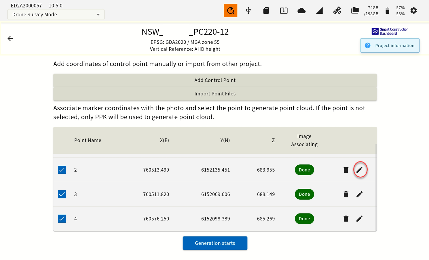
Tap the "Import Point File" button and specify a CSV file from displayed dialog, which contains coordinates of GCP. You may select “Add Control Point” if you manually add a control point.
-
Set the file format parameter according to the file and tap “OK”.
-
Tap edit button of each GCP to display a thumbnail of the image that may have the selected GCP in the image.
-
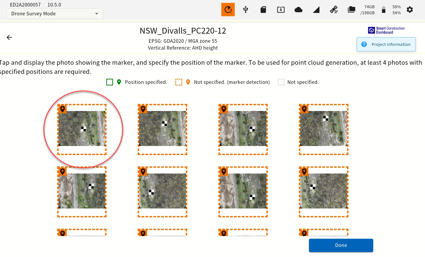
Tap the thumbnail of the image, align the center of the cross mark to the center of GCP in the image, and tap "OK" Automatically detected and highlighted in orange.
-
You can zoom in and out by pinching in and out, move the displayed portion by swiping. More than four images are required to align a GCP.
At least more than 1 GCP must be selected and aligned like this. If you proceed without selecting a GCP, point cloud is generated only with PPK.
-
When you finish matching the coordinates of the GCP (at least 4 of them) with the image center, tap the "Done" button. If the GCP center is confirmed it will be highlighted in green
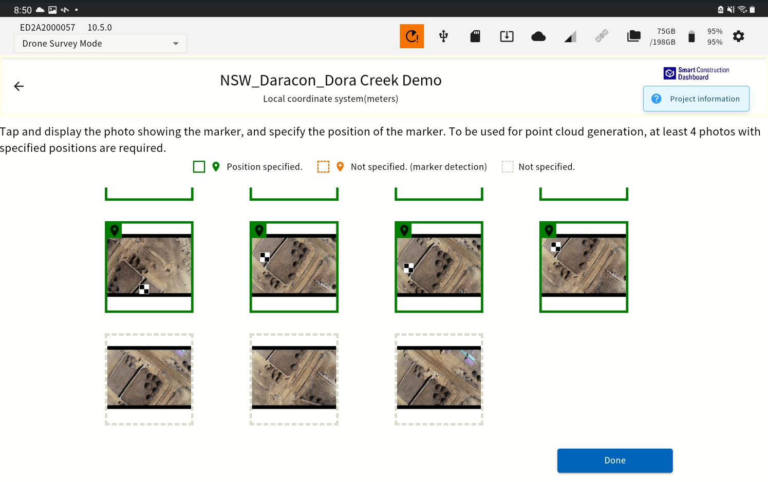
Tagging as many GCPs as possible improves accuracy.
-
Set the parameters of point cloud generation and tap the “Start” button.

-
The point cloud viewer screen shows up and the point cloud generation process starts. During this process, it is possible to switch to another window and perform the other work. You can check the generated point cloud by selecting it from the list on the project top screen.
To generate a Digital Elevation Model (DEM), both the Unwanted Object Analysis and Ortho Image Generation settings must be both ON.
View the generated point cloud
The right pane of the project top screen displays a list of point clouds and detailed information.
You can see the generated point cloud in the Point Cloud Viewer by tapping the list.
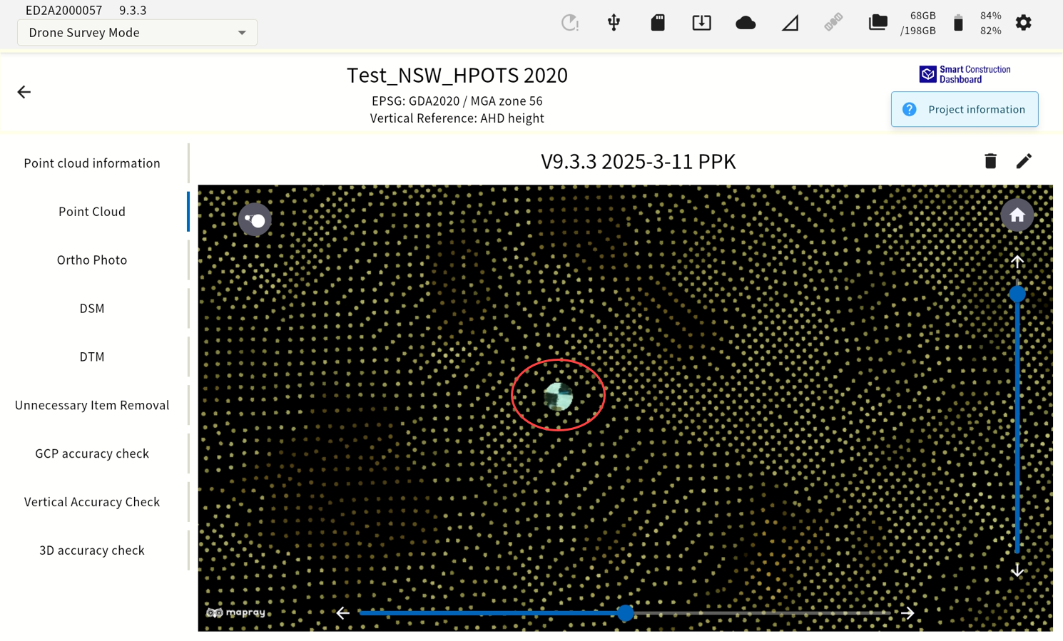
(e) Point Cloud Viewer Screen Part Names
Point Cloud information: Information about the point cloud
Point LCoud: Displays the generated point cloud
Ortho Image: Displayed only when the Ortho image option and DEM image option was "ON" upon the point group generation. Select to display the ortho image.
DSM/DTM: Displayed only when the Ortho image option, DEM image option and Unwanted Object analysis was "ON" upon the point group generation.
Vertical Accuracy Check: Enables you to verify the accuracy of the generated point cloud.
Unwanted Object Removal: Only displayed when Unwanted Object Removal was "ON" upon point
cloud generation. If this was selected, displays a point cloud with the Unwanted
Object Removal filter applied. You can also change the strength of the filter by tapping the icon .
The point cloud displayed in the Viewer area can be
・ Shrink/Enlarge: Pinch in/out
Vertical/Horizontal Rotation: The slider in the Viewer Area is displayed vertically and horizontally. You can also use the arrow buttons to fine-tune.
・ Reset: Tap the icon⌂ to reset the Viewer Area operation to the initial conditions
(f) Drone Flight Path Display (only when ortho image was generated)
-
Tap “Ortho Image” in the Point Cloud Viewer screen
-
Tap the icon in the upper left corner of the viewer.
Displays the flight path of the drone. Tap ○, then tap the "View Photo" button to show the image taken at that point.
(g) UNWANTED Object REMOVAL from the Point Cloud
EdgeBox's Unwanted Object Removal feature uses a proprietary algorithm to calculate the "Unwanted Object Likeliness" score, and you can change the filtering strength.
(i) To change the strength of point cloud junk removal
-
Tap “Unnecessary object Removal” in the Point Cloud Viewer screen.
-
Tap the icon in the upper left corner of the viewer and use the slider to adjust the strength of the unwanted object removal. 1 – 10, 10 beingthe strongest. Pay attentions to to how much is removed, you may have to use <10 .
(h) Point Cloud Accuracy Validation
To verify the accuracy of a point cloud, you need coordinates of the points you want to verify.
Place the CSV file which contains coordinates of check points included in the measurement area directly under the root folder of the USB memory in advance. Please refer to CSV format.
-
Insert USB memory into USB slot ④ on EdgeBox
Insert the USB memory into the USB3.0 port in the waterproof lid. The USB2.0 port outside the waterproof cover is for communication with the radio and cannot use for USB memory.
① Status LED
② SD card slot
③ Ether cable port
④ USB slot(USB3.0)
⑤ SIM card slot
⑥ Water-proof USB slot(USB2.0): cannot use this slot for USB memory.
-
Tap “Vertical Accuracy Check” in the Point Cloud Viewer screen.
-
Tap the “Import check point file” button and select the check point coordinate file to use for validation in the dialog that appears.
-
Set the file format parameter according to the file and tap “OK”.
-
Specify a range of point cloud around the check points to use for vertical accuracy check and tap “Start”.
The results shown in the screen.
Red character shows the out of tolerance. (+/-5cm)
You can redo or export the result to USB.
-
You can also correct (offset) the error in the Z axis. To offset the Z axis, turn on Error Correction in Z Axis.
Offset settings are applied when the generated point cloud is exported to the outside.
-
Additionally you can manually set a vertical offset to be applied by using the “Vertical offset by any value” function.
Important!
Validation cannot be performed if all check points are outside the point cloud range. Also, the error correction function in the Z-axis direction is not available when the validation is not performed.
Tips
Once you have verified it, you can reload it by reading the CSV again. When you revalidate, the validation results and the Z offset value are updated based on the most recent results.
Sending Point Clouds to a SMART CONSTRUCTION Dashboard
Before sending to the SMART CONSTRUCTION Dashboard, set the destination from the settings screen.
-
Launch the tablet app and select the project which contains the point cloud you want to send to the SMART CONSTRUCTION dashboard.
-
Tap “Upload Generated Data”.
Displays a list of point clouds generated in the selected project.
-
Tap the check box of the point cloud to send.
You can also select multiple point clouds.
-
Select the destination and tap “Send”.
The SMART CONSTRUCTION dashboard work site list appears.
If you can't find the right destination, check your account logging in.
Tips
You can check the status of your message after it has been sent by tapping the icon on the status bar. You can also check the progress and cancel the submission on this screen.
Exporting Data
(i) EXPORT GNSS logs to USB memory
To perform PPK on other systems, etc., you will need to export the GNSS log from EdgeBox.
-
Insert USB memory into EdgeBox
Insert the USB memory into the USB3.0 port in the waterproof lid. The USB2.0 port outside the waterproof cover is for communication with the radio and cannot use for USB memory.
⑦ Status LED
⑧ SD card slot
⑨ Ether cable port
⑩ USB slot(USB3.0)
⑪ SIM card slot
⑫ Water-proof USB slot(USB2.0): cannot use this slot for USB memory
-
Launch the tablet app and select the project from which you want to export GNSS logs to USB memory
-
Tap “Manage PPK Log”
-
Displays the list of GNSS logs for the selected project.
-
To export to USB memory, tap the check box of the GNSS log to check it, and then tap Export
You can also select multiple logs.
A dialog appears when the export is complete.
-
Remove the USB memory
Tap the USB icon on the status bar to see the message that the USB memory can be safely removed, and then unplug the USB memory.
(j) Exporting Point Cloud Data to USB Memory
-
Insert USB memory into EdgeBox
Insert the USB memory into the USB3.0 port in the waterproof lid. The USB2.0 port outside the waterproof cover is for communication with the radio and cannot use for USB memory.
① Status LED
② SD card slot
③ Ether cable port
④ USB slot(USB3.0)
⑤ SIM card slot
⑥ Water-proof USB slot(USB2.0): Cannot use this slot for USB memory
-
Launch the tablet app and select the project that contains the point cloud data to export to USB memory
-
Tap “Export Generated Data to USB”
Displays a list of point clouds generated in the selected project.
-
Tap the check box of the point cloud to export to USB memory.
You can also select multiple point clouds.
-
Select a point cloud coordinate system and tap “Export”.
You can select local coordinate system which you have selected when you created the project, or WGS84 coordinate system. And file type “.Las or .txt”
A dialog appears when the export to the USB memory completed.
-
Remove the USB memory
Tap the USB icon on the status bar to see the message that the USB memory can be safely removed, and then unplug the USB memory.
Tip: Always press the eject icon to eject the USB properly. Failure to do so may result in corrupt data or the USB becoming unusable.
Load GNSS logs
-
You can load GNSS logs from one EdgeBox to another.
-
Insert a USB memory containing data from a EdgeBox
Insert the USB memory into the USB3.0 port in the waterproof lid. The USB2.0 port outside the waterproof cover is for communication with the radio and cannot use for USB memory.
① Status LED
② SD card slot
③ Ether cable port
④ USB slot(USB3.0)
⑤ SIM card slot
⑥ Water-proof USB slot(USB2.0): cannot use this for USB memory
-
Select a project to import logs from.
-
Tap “Manage PPK Log“
-
-
Tap “Import“.
-
The GNSS log in the USB memory will be loaded.
To Send GNSS logs to Smart Construction Dashboard Cloud SfM
Customers who subscribe to Cloud SFM for SFM processing at large sites can use this function to upload PPK logs.
To process PPK SFM using Cloud SFM, tap the corresponding PPKLOG and then tap (Send to Cloud).