
WHEN WE USE GCPS TO IMPROVE THE ACCURACY
If Edge 2 cannot be included in the drone photo, a GCP marker can be used to improve the accuracy of the point cloud. When Edge 2 is included in the drone photo, it serves as a GCP, allowing high accuracy with PPK-only processing. Please prepare the drone image with GCPs and coordinate information of GCP.
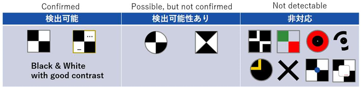
In v10, when performing SFM processing using GCPs, the positions of the following markers can now be automatically detected.
Detectable markers
-
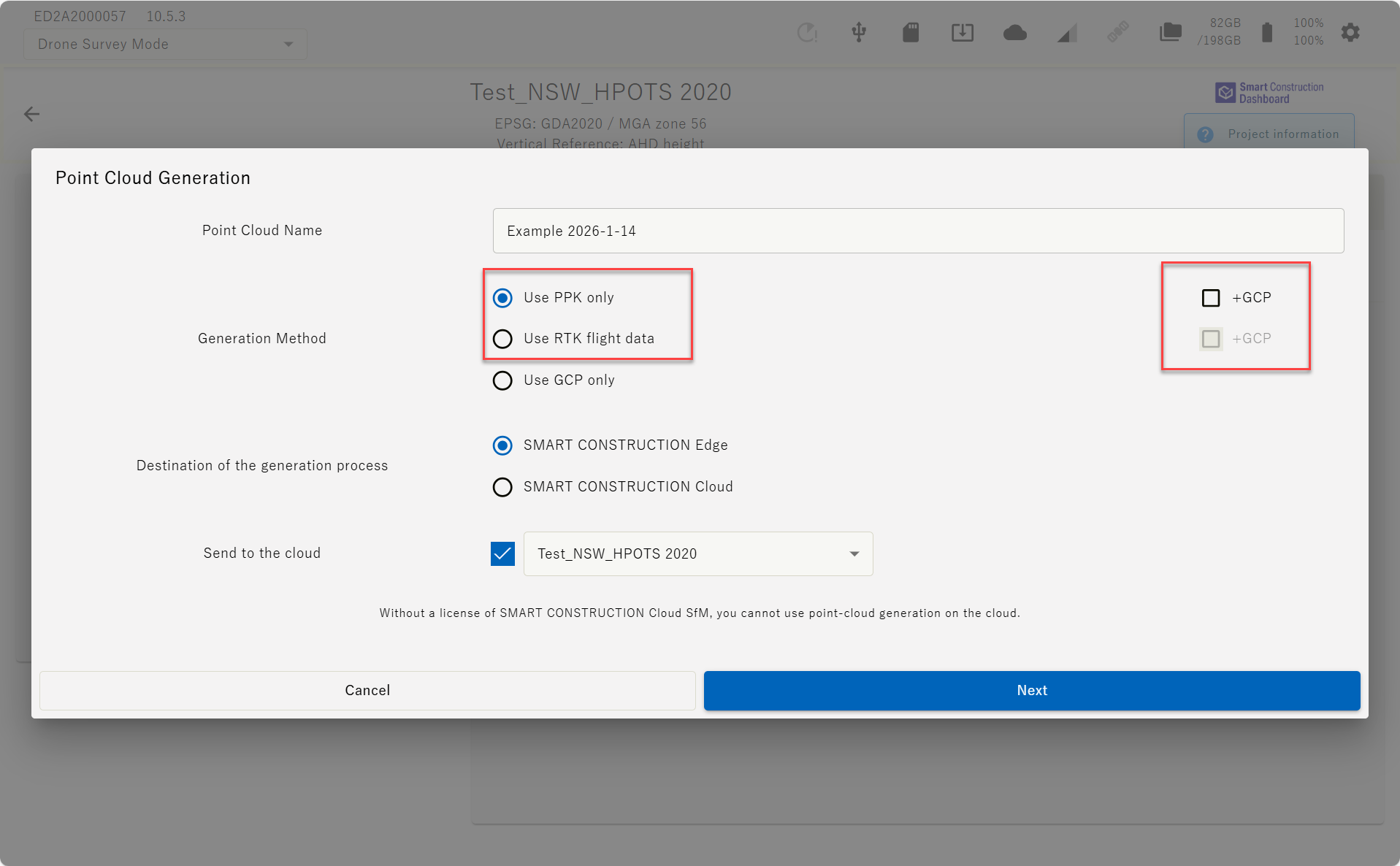
Select "Use PPK and GCP" in step 4 of "Generating Point Clouds".
-
Tap the "Import Flight Data" button and select the drone data to upload to the EdgeBox from the displayed dialog.
-
The imported data will be listed. You can also select and multiple imported data.
-
Check the flight data to generate point cloud from the imported data list and tap "PPK processing start" button.
※If you want to automatically upload the point cloud, check (Send to cloud) and select the upload destination.
-
A dialog showing the PPK Fix rate will appear, check the rate and press "Next"
A low PPK Fix rate may affect the accuracy of the resulting point cloud. At the point where the red × mark on the drone flight route has a worse acquisition of the drone location. Please confirm and fly again if necessary.
-
Check the flight data to generate point cloud from the imported data list and tap " Start PPK processing" button.
“Use GCP only” This is a preliminary functional update based on future updates and will enable GCP-only SFM processing for P4RTK, M3E, and M300. We have confirmed the accuracy, but if there is no need for GCP-only processing, we recommend normal PPK/RTK or +GCP processing for the models listed above at this time.
-
We will show the details of the setting items from the next page.

-
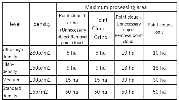
※If you tap ''Conditions which was able to generate point cloud'' The number of photos loaded and the maximum number of photos processed at each density can be checked.
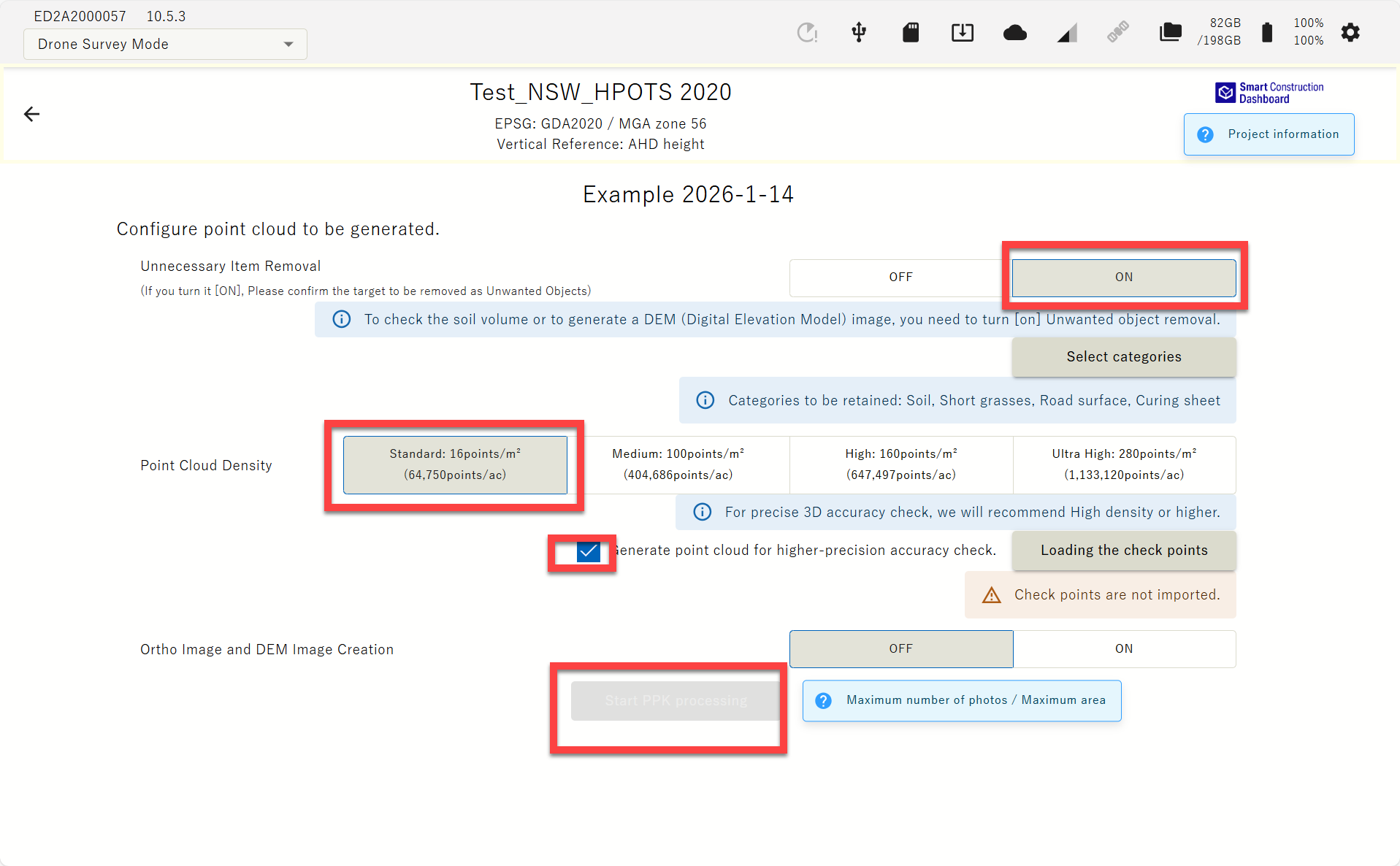
Unnecessary object removal: When you toggle ON, it removes unnecessary objects, such as buildings and vehicles, that are not needed for soil volume calculations. Press “Select Category” to choose the category for removal.
“Short grasses" can remove/retain all Short grasses, other vegetation such as tall trees will be removed and "Road Surface" can remove/retain road surfaces, including concrete. The “curing sheet” could remove/retain a green or blue sheet on site.
Point Cloud Density :Adjusts the density of the point cloud Tips 3D accuracy check requires Ultra high density . There’s area size limitation with this setting.
Ortho and DEM image generation: Generate ortho (sky photo) and DEM (Digital Elevation Model).
If you do not turn on the ortho generation, you will not be able to output an image showing the verification point positions on the ortho, which is the 3D accuracy check report material.
-
Insert the USB memory with GCP coordinates file (.csv) in the USB slot of SMART CONSTRUCTION Edge.
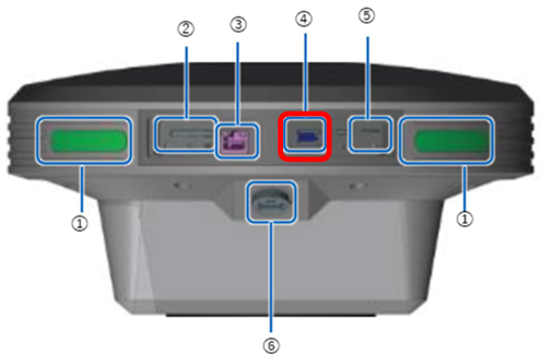
Insert the USB memory into the USB slot (inside the waterproof lid) ④ of the EdgeBox
① Status LED
② SD card slot
③ Ether cable port
④ USB slot(USB3.0)
⑤ SIM card slot
⑥ Water-proof USB slot(USB2.0): cannot use this slot for USB memory 1
-
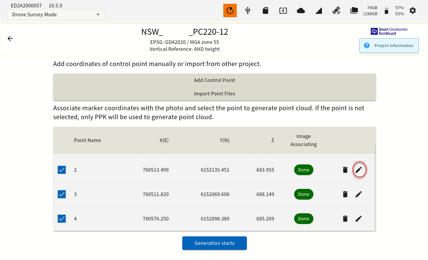
Tap the "Import Point File" button and specify a CSV file from displayed dialog, which contains coordinates of GCP. You may select “Add Control Point” if you manually add a control point.
-
Set the file format parameter according to the file and tap “OK”.
-
Tap edit button of each GCP to display a thumbnail of the image that may have the selected GCP in the image.
-
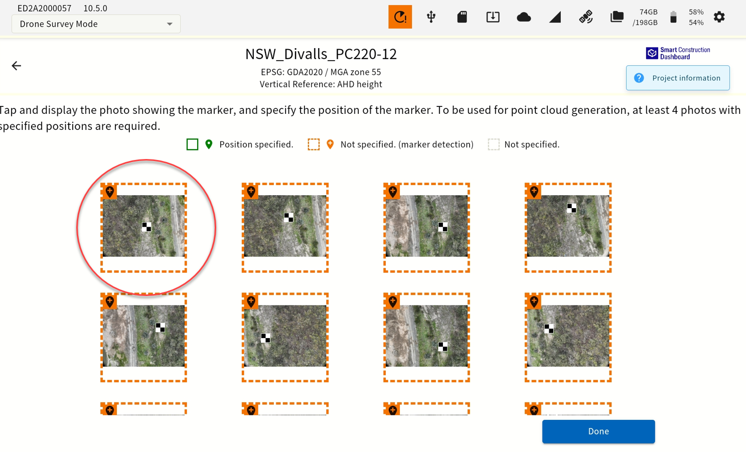
Tap the thumbnail of the image, align the center of the cross mark to the center of GCP in the image, and tap "OK" Automatically detected and highlighted in orange.
-
You can zoom in and out by pinching in and out, move the displayed portion by swiping. More than four images are required to align a GCP.
At least more than 1 GCP must be selected and aligned like this. If you proceed without selecting a GCP, point cloud is generated only with PPK.
-
When you finish matching the coordinates of the GCP (at least 4 of them) with the image center, tap the "Done" button. If the GCP center is confirmed it will be highlighted in green
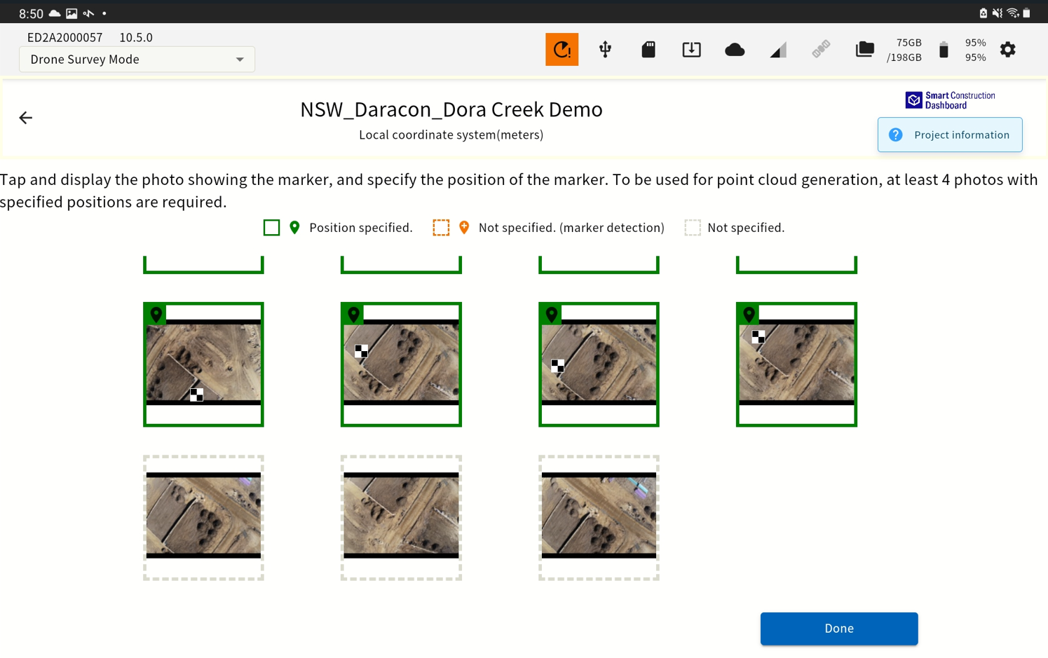
Tagging as many GCPs as possible improves accuracy.
-
Set the parameters of point cloud generation and tap the “Start” button.
-
The point cloud viewer screen shows up and the point cloud generation process starts. During this process, it is possible to switch to another window and perform the other work. You can check the generated point cloud by selecting it from the list on the project top screen.
To generate a Digital Elevation Model (DEM), both the Unwanted Object Analysis and Ortho Image Generation settings must be both ON.