Name of each part
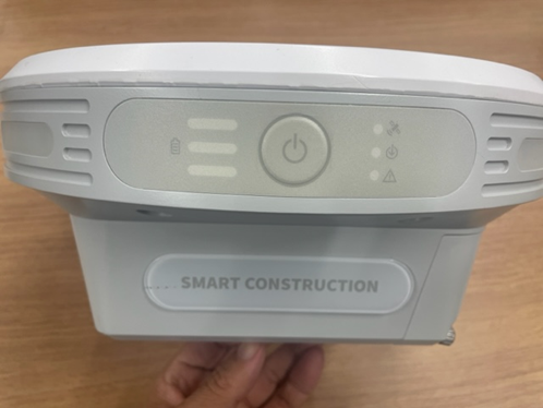
(a) Edge Body Part Name
Front of the body
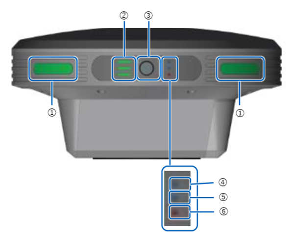
① Status LED
② battery indicator
③ power button
④ GNSS Receive Status LED
⑤ PPK Logging Status LED
⑥ Error/Sub-microcomputer Update LED
Body Right Side
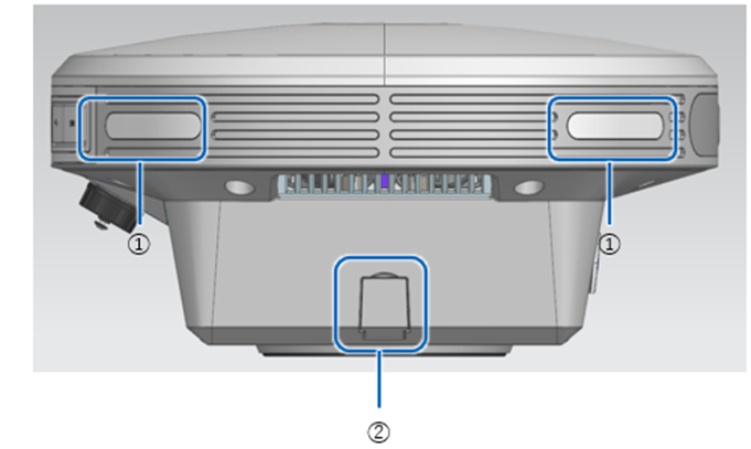
① Status LED
② AC Adapter Inlet
Body Left Side
① Status LED
② Battery Inlet (Inside Lid)
③ battery lid screw
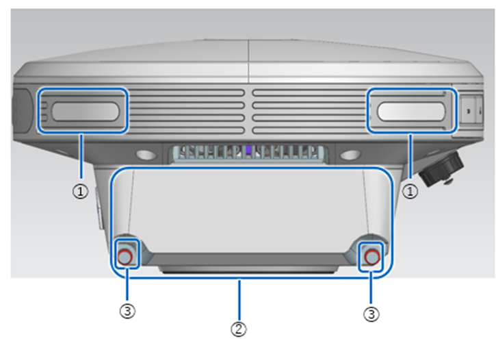
Back of the body

① Status LED
② SD card slot
③ Ether Cable Terminal
④ USB Slot (USB3.0)
⑤ SIM CARD SLOT
⑥ Waterproof USB Slot (USB2.0)
(b) Name of each part of the status bar
① mode switching
Tap to switch between drone survey mode and base station mode.
② Running job icon
Tap to list the jobs running in the background.
③ USB Memory Icon
Displays whether USB memory is recognised. Tap this icon when removing USB memory.
④ SD card icon.
Displays whether SD card is recognised. Tap this icon when removing SD card.
⑤ Exported data list Icon
Shows the exporting status to USB memory.
⑥ Upload List Icon
Shows the uploading status to the SMART CONSTRUCTION dashboard.
⑦ LTE icon
Displays the status of the LTE.
⑧ GNSS icon
Displays the status of GNSS reception. Tap to view the Acquired Satellite list.
⑨ Storage
Displays the amount of storage remaining on the unit.
⑩ Battery icon
Shows the amount of battery life for each of the two batteries.
⑪ Settings icon
(c) Components
Main unit:
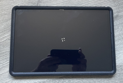
Tablet:
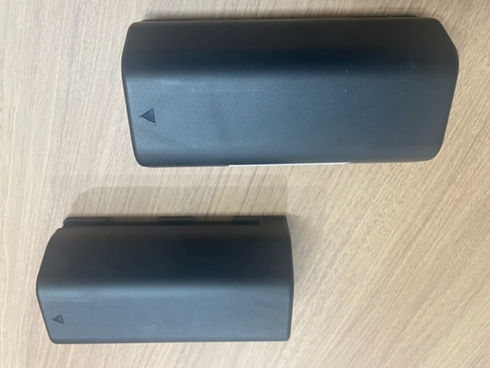
Batteries (pair):
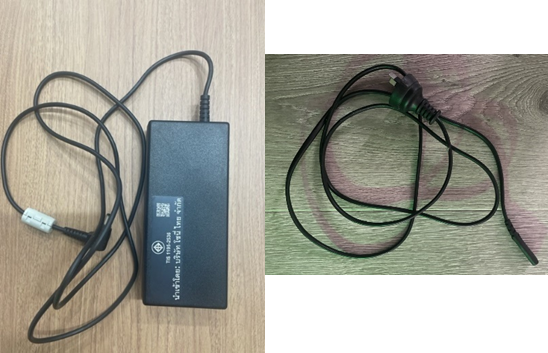
AC adopter and Power cable:
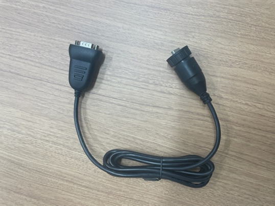
Water-proof USB-Serial conversion cable:
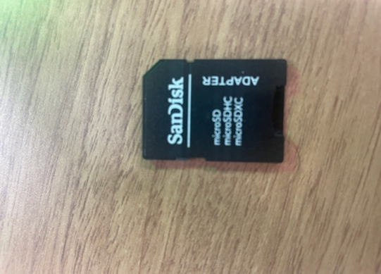
SD card adaptor:
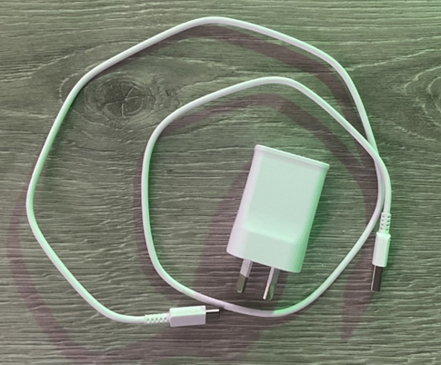
Tablet Charger:
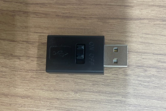
USB Extender: