
New Features
Create a 3D Polyline from Measured Points
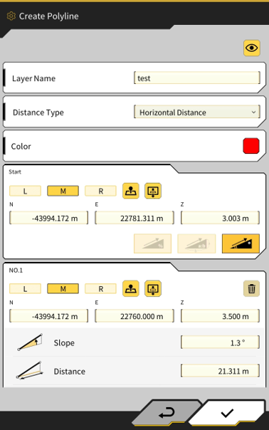
Polylines can now be created from points measured with the bucket edge, or from entering coordinate values.
The created polylines can be used in functions such as creating a design surface from linework and in the steer indicator function.
Create Polyline feature can be access in 2 areas;
-
Menu → Project File →


-
Side Menu on Main User Interface -
Note - Polylines created within app can only be used on the tablet which they were created
Create Polyline
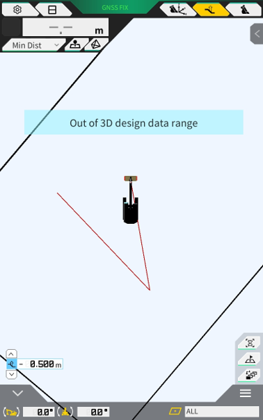
Example of created polylines on user interface
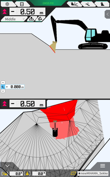
Heatmap Colours reflect applied Vertical Offset
Heatmap colours now change based on design surface vertical offset applied
Previously, even if the design surface was offset, the heatmap displayed differences from the pre-offset design surface.
It has been improved to display differences from the post-offset design surface.
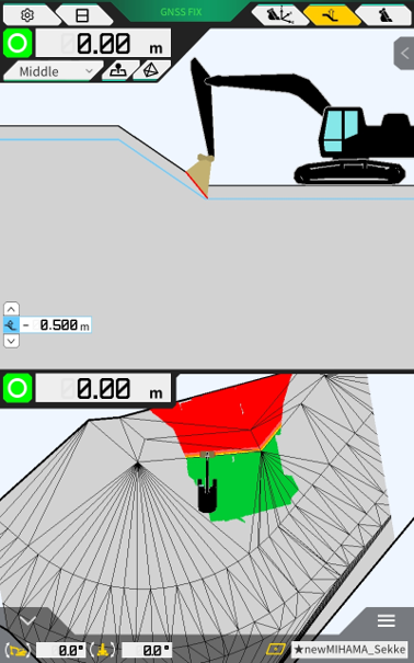
When the design surface offset value is changed, the heatmap coloring switches to reflect the new offset.
Without Design Surface Offset
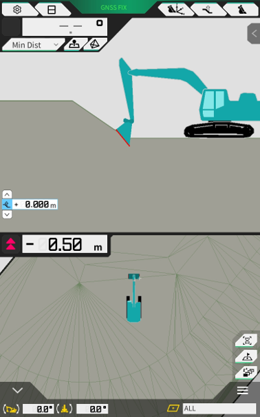
With Design Surface Offset (-0.5m)
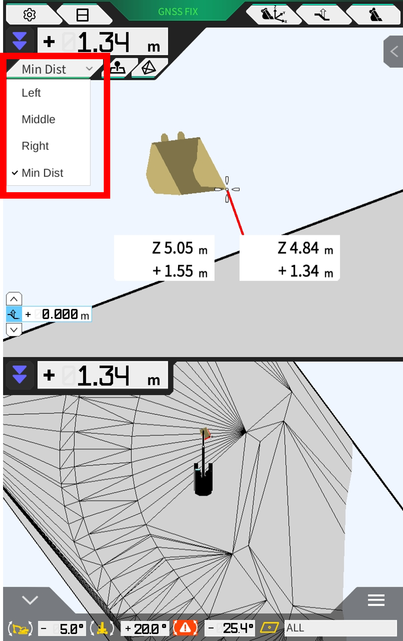
New Bucket Reference Point - “Min Dist”
A new reference point (Min Dist - Minimum Distance) has been added which automatically switches the bucket reference position base on the closest reference point to the design surface.
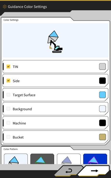
Customisable Colour Settings for Machine and Bucket
The colours of the machine and bucket graphics can now be changed in Guidance Settings. There is a predefined colour list, and colours can also be entered in using HEX colour code.
Menu → Guidance Settings → Guidance Color (Colour) Settings
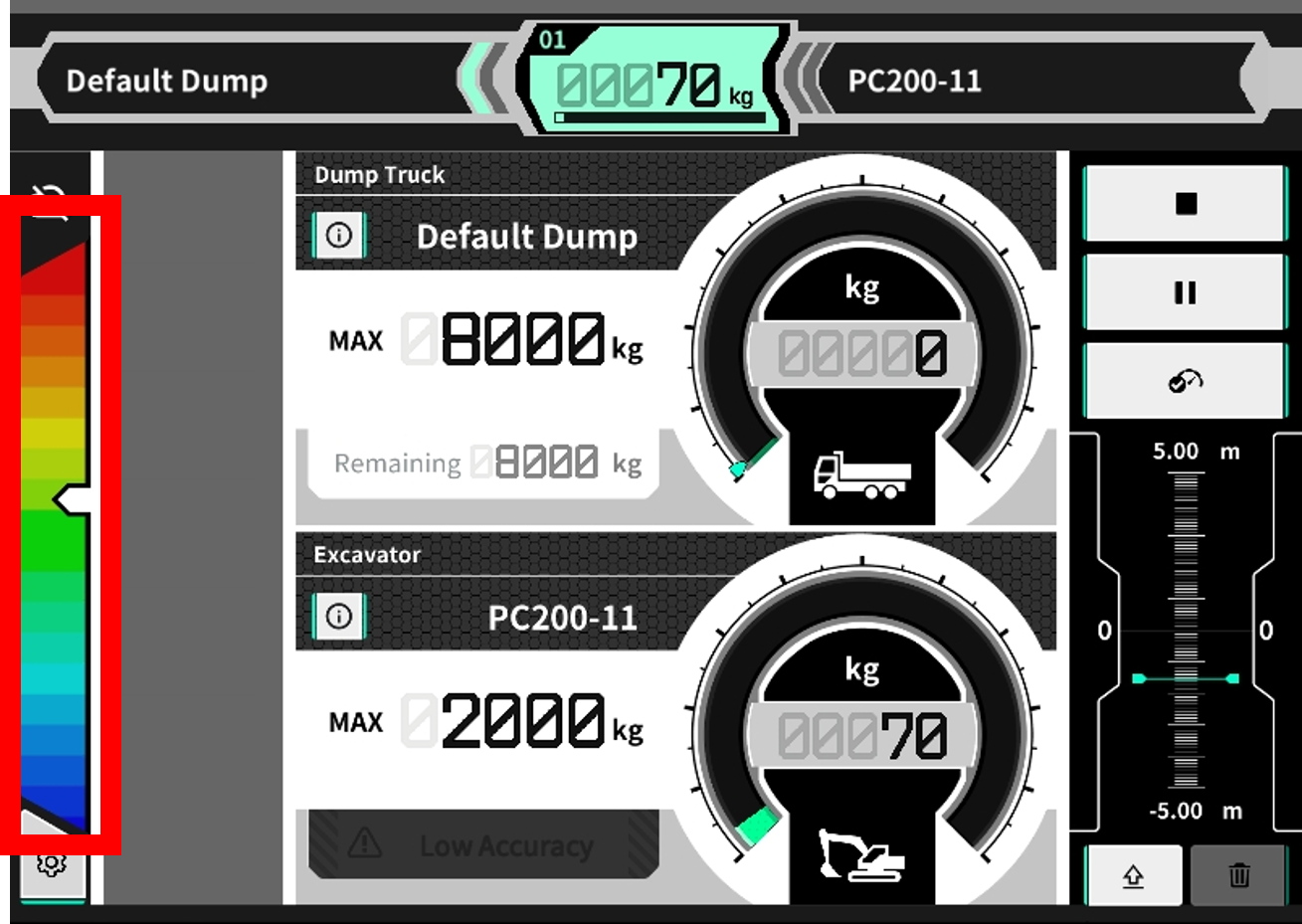
New Boom Up Speed Indicator on Payload Interface
The boom raise speed during unloaded calibration is used as the baseline and is displayed on this bar during the loading operation.
The Center (Green in this example) shows the boom raising speed during the unloaded calibration.
Note: This feature is being deployed as a guide/assistance feature and will potentially undergo further changes and improvements based on user feedback in future.
An unloaded calibration must be performed using this new software in order to obtain the boom up baseline speed.
Other Updates and Misc Fixes
-
Bug Fixes/Improvements to the NTRIP configuration screen
-
Fixed an issue with intermittent freezing on ntrip screen
-
Improved scroll usability on large mount point lists
-
-
Modified topographic survey point saving interface to allow selection of bucket edge
-
Made changes to payload calculation logic to account for diminishing accuracy when arm is moved during loading cycle
-
Modified the system to ignore pressure sensor data when system is licensed for 3DMG only