
This function is available with tablet app version 1.0.04 or later. If you are using an older version, please update the app.
Introduction
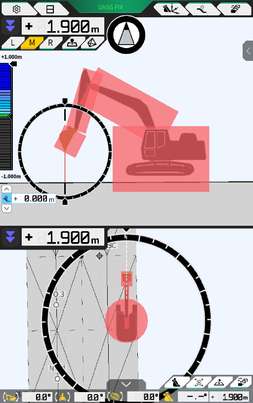
Geofence function places 3D obstacles on the design surface and alerts the user if a construction machine approaches or comes into contact with them.
This function can be used to avoid contact hazards such as buildings and piping.
Important
The geofence contact detection/alert notification function may not function properly depending on the environment and conditions in which it is used. Do not overconfidently use the function and make sure you understand the function and conditions of use.
Geofence is not available for 2 Piece Boom and Swing Boom at this moment
Feature Overview
How to use
Activate Function
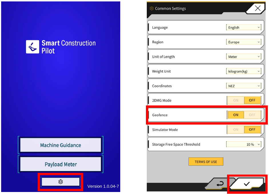
Geofence can be activated in the common settings.
-
Launching the tablet app
-
Tap ⚙
-
Turn ON “Geofence”
-
Tap ✓ (save settings)
Geofence Basic Settings
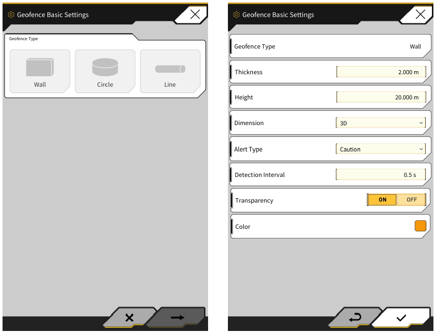
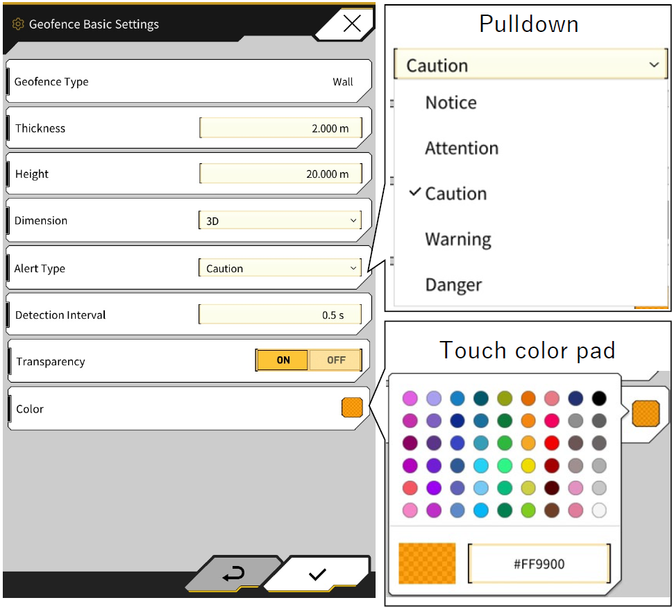
Each of the three types (Wall, Circle, and Line) can be set and will be reflected in the default parameters for geofence creation(Each parameter can be changed at the time of creation).
-
Launch Machine Guidance Screen
-
⚙Menu
-
Geofence Settings
-
Geofence Basic Settings
|
Type of Geofence |
Sample |
Configuration Options |
Common Function |
|---|---|---|---|
|
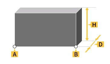
Wall |
|
|
・Used for buildings, fences, etc.
|
|
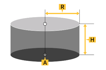
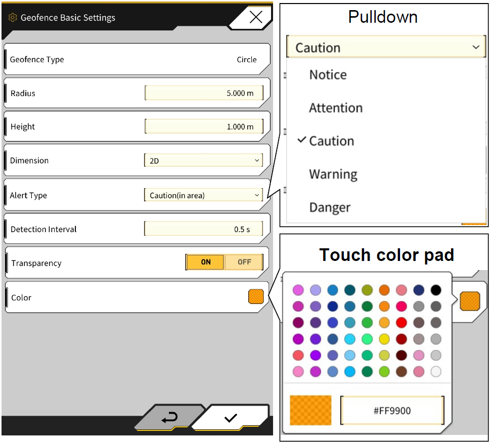
Circle |
|
|
・Used for reference points, danger areas, etc.
|
|
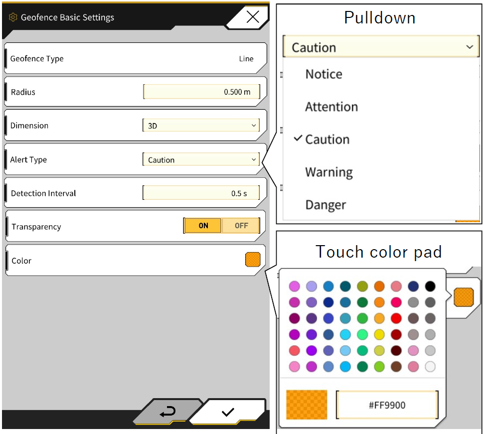
Line |
|
|
・Used for waterways, power lines, etc.
|
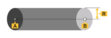
Wall Geofence Settings
Circle Geofence Settings
Line Geofence Settings
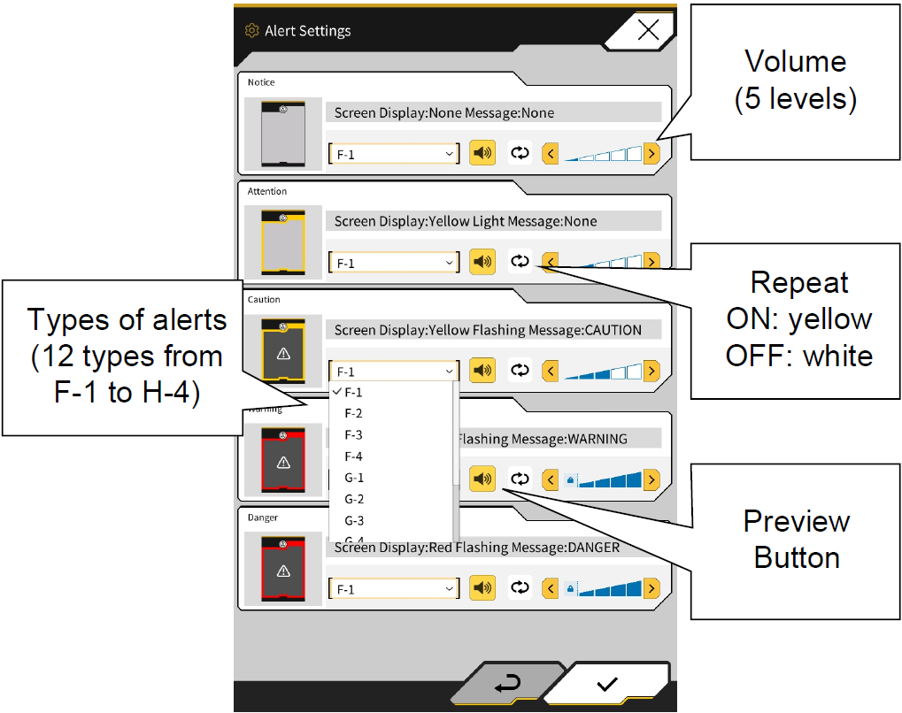
Setting Alert Parameters
For each of the five types of alerts set for geofences, you can set the type of alert, volume, and whether or not it repeats.
-
Launch Machine Guidance Screen
-
⚙Menu
-
Geofence Settings
-
Alert Settings
Collision Detection Settings
The collision detection settings are used to detect proximity and contact with geofences. The following two settings can be changed in the collision detection settings. Depending on the conditions of use and other factors, you can set a larger value for detection with more leeway.
-
Collision Detection Area of Work Equipment
-
Collision Detection Angle and Body Area
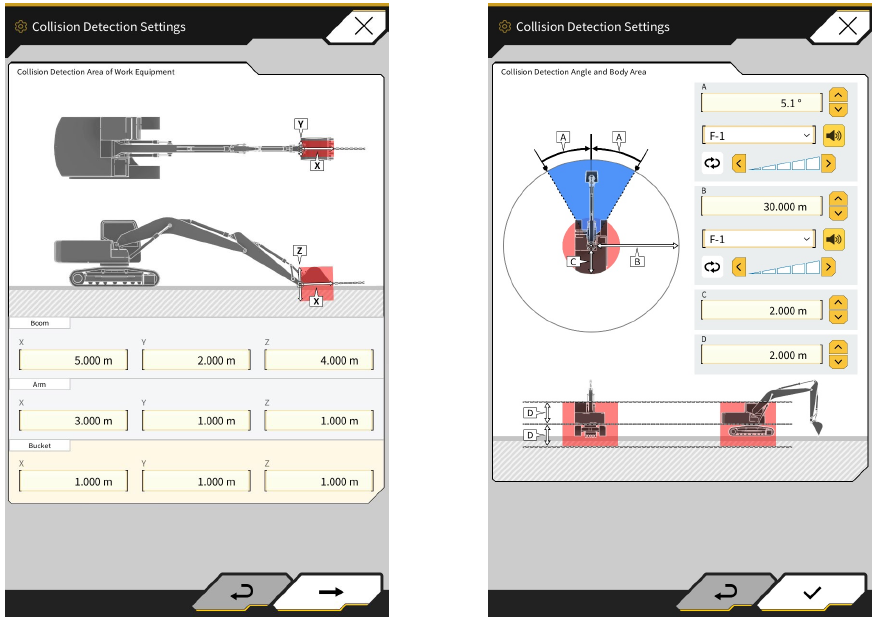
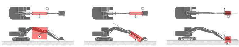
Collision Detection - Area of work equipment
Set the area that will be alerted when the work equipment contacts the geofence. Measure and enter XYZ values for the boom, arm, and bucket, respectively.
-
Enter the values for the shape of the boom. In particular, the Z value must be entered in consideration of the geometry.
-
Enter the values for the shape of the arm.
-
Enter the values for the shape of the bucket
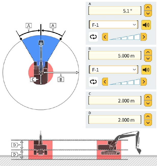
Collision Detection - Angle and Body area
Sets the area to detect when a construction machine is approaching a geofence, the area to notify when there is a risk of contact with a geofence when turning, and the area to be alerted when the vehicle body contacts a geofence
-
You can set the angle of contact with the geofence when turning. If there is a geofence within the detection area, the radar will change to yellow in the guidance screen
-
You can set the radius within which geofences are detected. If there is a geofence within the radius, the radar will be displayed on the guidance screen
-
The contact radius of the vehicle can be set
-
The contact height of the vehicle can be set
Check Detection Area
To check the detection area set on the guidance screen, turn on the "Detection Area Display Mode" according to the following procedure.
-
Tap Menu (⚙) on the Guidance screen
-
Tap Guidance Settings
-
Tap Application Settings
-
Turn on “Detection Area Display Mode” for Geofence
-
Tap the tick in the lower right corner to save settings
The size, shape, etc. of the displayed car body differs from the actual car body. Be sure to make settings based on actual measurements.
Once the detection area has been confirmed, set “Detection Area Display Mode” should be set to OFF by repeating the steps above.
Geofence
Geofence Creation
Create a Geofence and place it on the design data.
-
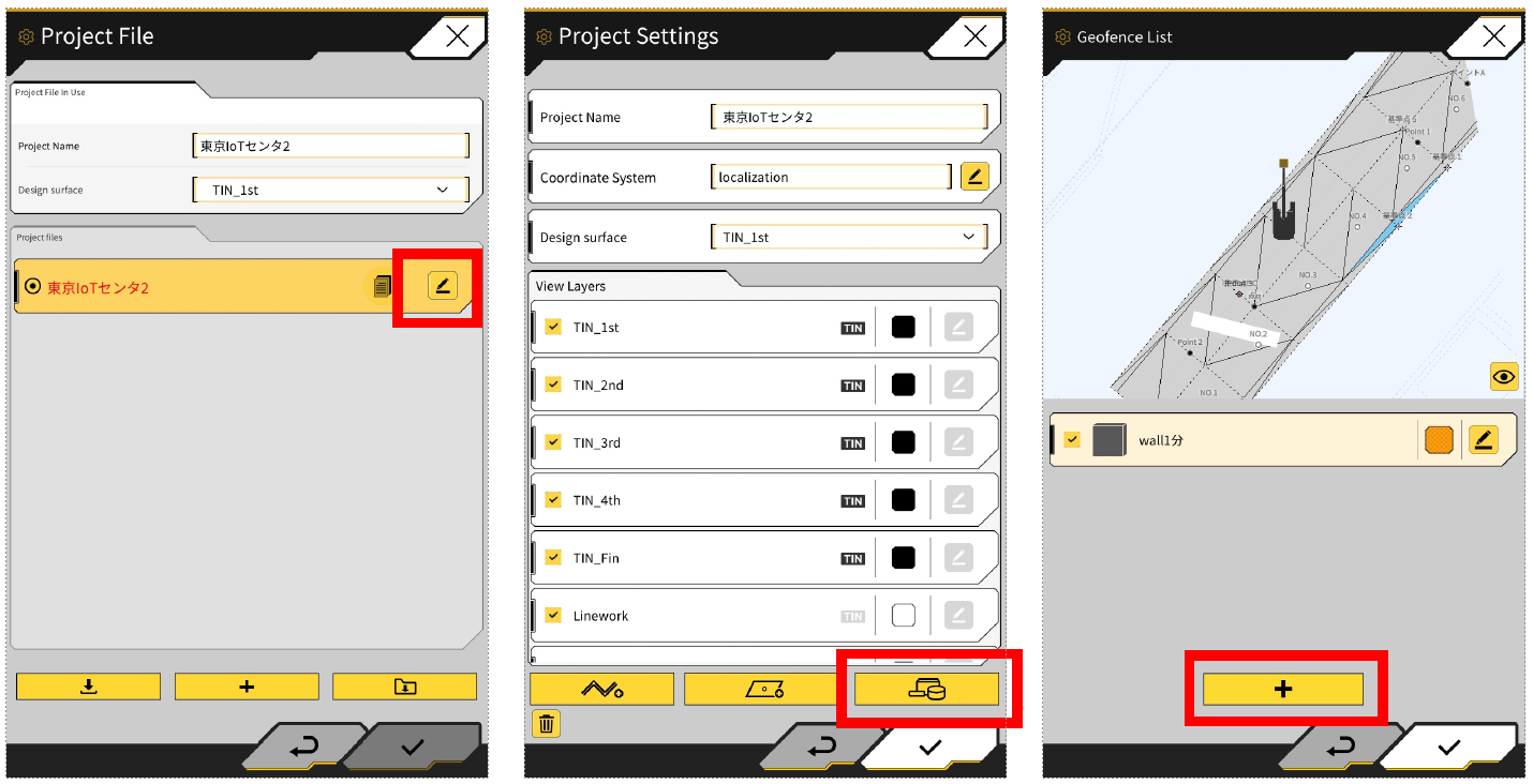
Machine Guidance Menu > Project File
-
Tap the edit (pencil) icon on Profile File
-
Tape the yellow icon with the shapes (circle, rectangle etc)
-
Go to the Create New Geofence screen
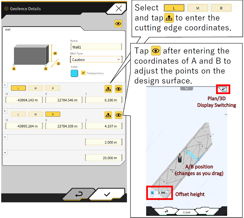
Wall Type Creation
-
Create New Geofence Screen, Select Wall and press the tick
-
Enter name
-
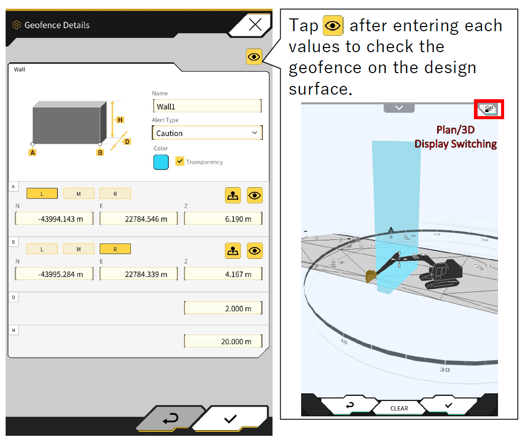
Set each parameter and press the tick to save
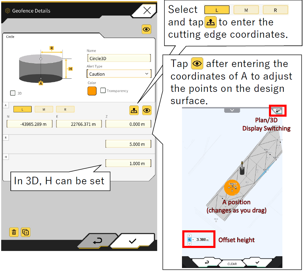
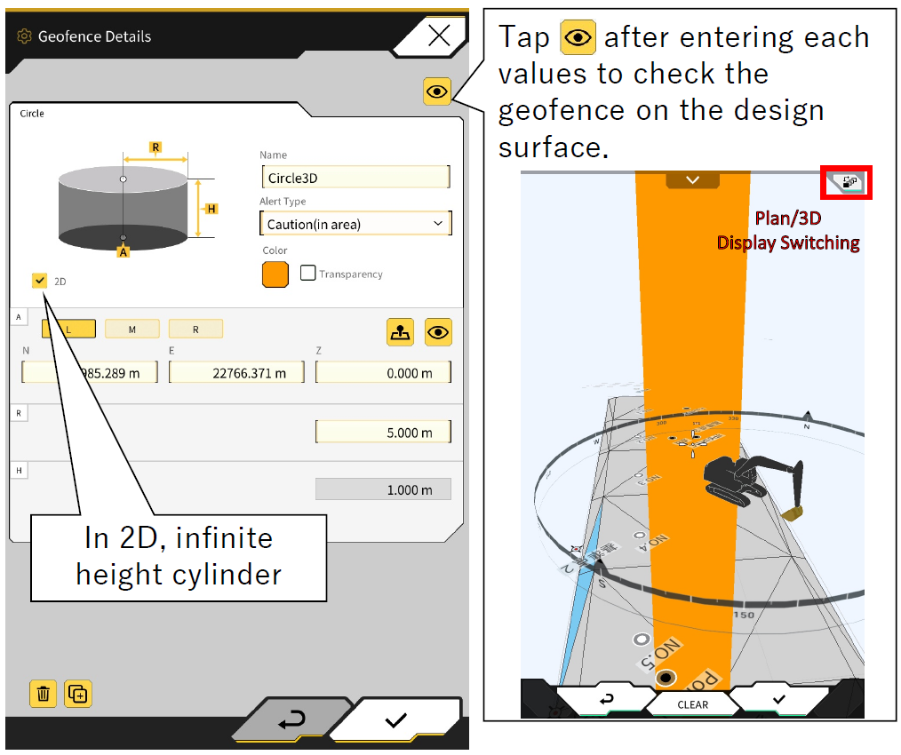
Circle Type Creation
-
Create New Geofence Screen, Select Circle and press the tick
-
Enter name
-
Set each parameter and press the tick to save
If 2D is ticked, the height H cannot be entered and the alert type can be selected "construction equipment in contact(in area)" or "construction equipment out of area from within geofence (out of area)".
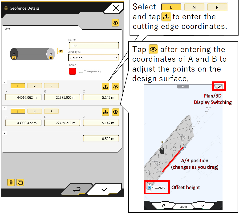
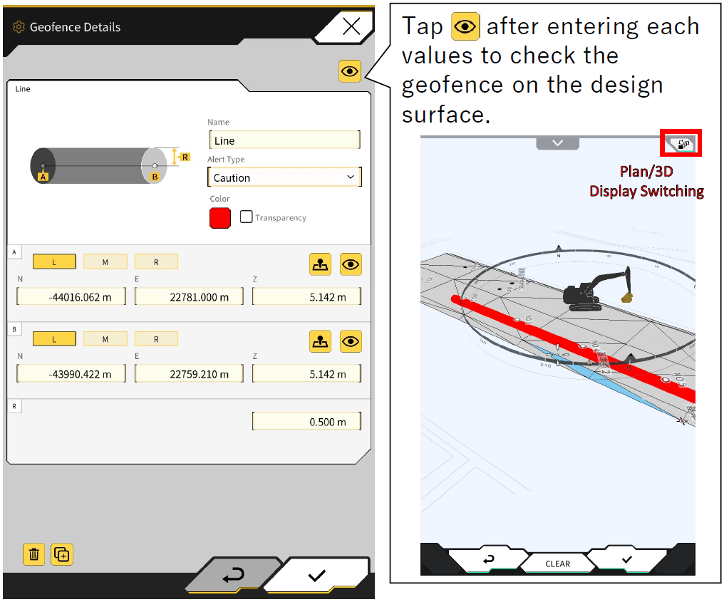
Line Type Creation
-
Create New Geofence Screen, Select Line and press the tick
-
Enter name
-
Set each parameter and press the tick to save
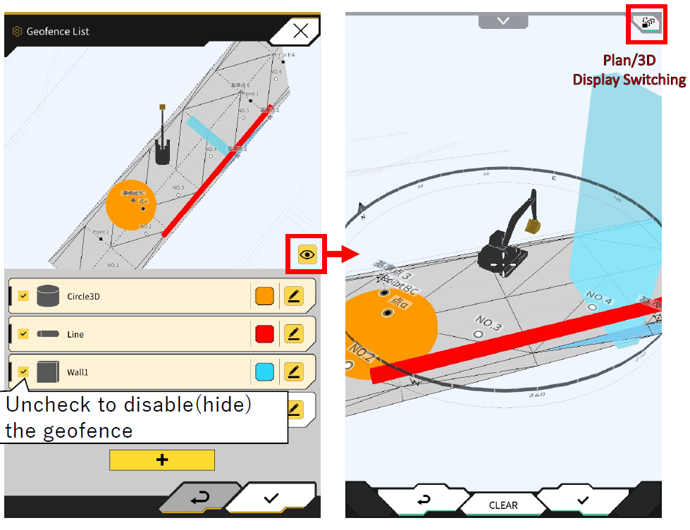
Geofence Confirmation
The Geofence List screen allows you to check the type, name, color, location, and enable/disable settings for the list of geofences you have created.
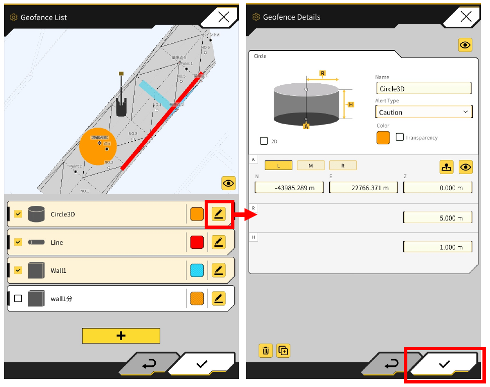
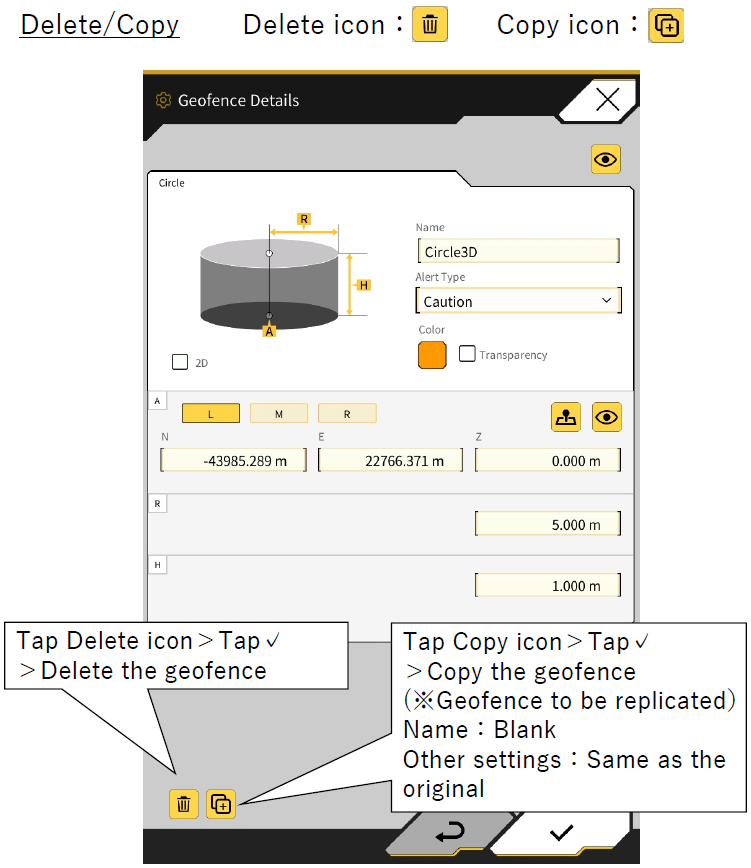
Edit Geofence
Geofence Details screen allows you to edit, delete, or copy for a geofence that has already been created.
Notes
-
Contact Smart Construction Support Centre for further information