
The following is an explanation of the Komatsu GX55 Control Box which is installed on all iMC Bulldozers prior to release to the customer. To perform suitable operations correctly and safely, it is important to completely understand methods of operating the equipment, and the meanings of the displays.
|
WARNING To prevent the blade from moving suddenly, turn on the control box power only when performing work with “intelligent Machine Control”. |
The control box has 2 functions,
-
A function to set or adjust the design surface to be used for the blade automatic control; and
-
A function to display the GNSS satellite information.
The following diagram shows the display screen. It is a Touch Screen. Simply touch it directly to operate it.
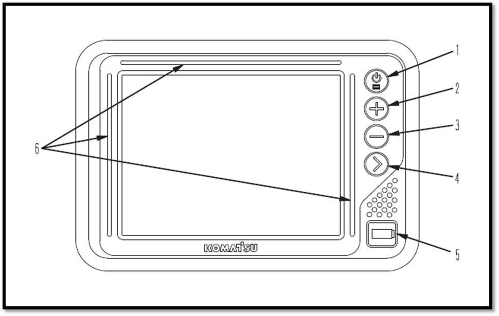
(1) Power ON/OFF and menu switch
(2) Zoom in switch
(3) Zoom out switch
(4) Toggle main view switch
(5) USB port
(6) LED indicator
Things to note when checking the functions of the control box prior to commencing any task on the work site:
-
Position the machine on level ground under the open sky.
-
Turn the base station power on (see How to set up a Base Station)
-
Turn the control box power on to perform the checks or work with the iMC.
(note: If the control box starts operation on a slope and pitching angle or rolling angle is 20° or more, the accuracy may deteriorate. Therefore, it’s important to start the control box when the machine is on a level surface).
-
The power supply of the control box is not linked with the starting of the machine, so the control box will not automatically turn on or off when the machine starts and stops. The control box must be turned on or off using the on/off switch on the control box
-
There is no priority in the order between switching the control box on or off and starting the machine.
-
The control box operates on a Windows® operating system.
-
After turning the control box on, it takes approximately 2 minutes until the Windows® operating system starts and the main window is displayed. In the same way, after turning the control box off, it takes approximately 2 minutes until the main window is finished and Windows® operating system shuts down
Network Modem
The network modem is a necessary terminal for 3G communication to obtain the satellite information via a network connection and connect the construction management system such as the Sitelink3D.
When using the network modem, Komatsu recommends using Komatsu genuine network modem antenna (option). If a non-genuine antenna part is used, it may not comply with the regulations in the country or area where the machine is being used. This is because the network modem is a wireless device which uses radio wave and the usage of radio waves are regulated.
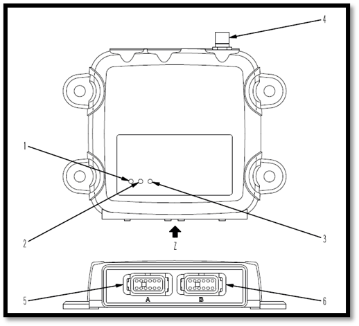
(1) Power supply LED Indicator
(2) Communication LED Indicator
(3) Bluetooth LED Indicator
(4) Antenna connecting port
(5) Connector port 1
(6) Connector port 2
How each LED indicator works
Power supply LED Indicator (1)
|
Lighting colour |
Status |
|
Green |
ON |
|
Not lit |
OFF |
Communication LED Indicator (2)
|
Lighting colour |
Status |
|
Not lit |
OFF |
|
Yellow |
Starting up |
|
Flashing Green |
Not connecting to the Sitelink3D server. (No GPRS connection information is being received) |
|
Green |
Connection to the Sitelink3D server is established, but no GNSS compensation information is obtained |
|
Flashing Green & Red |
Connection to the Sitelink3D server is established, and GNSS compensation information is received. |
Bluetooth LED Indicator (3)
|
Lighting colour |
Status |
|
Not lit |
Connection to Bluetooth is not established |